Navigation
Install the app
How to install the app on iOS
Follow along with the video below to see how to install our site as a web app on your home screen.
Note: This feature may not be available in some browsers.
More options
You are using an out of date browser. It may not display this or other websites correctly.
You should upgrade or use an alternative browser.
You should upgrade or use an alternative browser.
229s21
http://www.twitt.org/Farnborough.html#directory
General
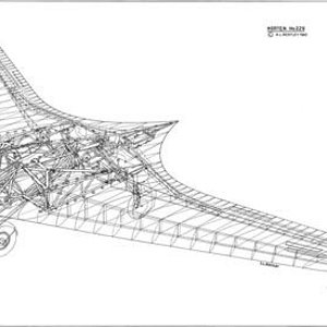
The H IX was a single seat fighter bomber of 16 m span with twin jet engines, being a further development of the H V and H VII designs. Fig. 19 is a general arrangement drawing made from a wooden model found at Gottingen, where the first two of the type were built.
Four aircraft of the H IX type were started, designated V.1 to V.4. V.1 was the prototype, designed as a single seater with twin B.M.W. 003 jets, which were not ready when the airframe was finished. It was accordingly completed as a glider (Fig. 20) (not reproducible) and extensively test flown. D.V.L. instrumented it for special directional damping tests to determine its suitability as a gun platform. V.2 was completed (also at Gottingen) with two Juno 004 units and did 2-hours flying before crashing during a single engine landing. The pilot (Ziller) apparently landed short after misjudging his approach. V.3 was being built by Gotha at Friedrichsrodal as a prototype of the series production version. V.4 did not get beyond the project stage but was to be a two-seater night fighter with an extended nose to house the extra man (Fig. 19) (missing).
In shape, the H IX was a pure wing with increased chord at the center to give sufficient thickness to house the pilot and the jet units, which were placed close together on either side.
Aerodynamic Design
The H IX started as a private venture and the Hortens were very anxious to avoid failure so they avoided aerodynamic experiments wherever possible. A lower sweepback was used than on the H V and H VII and laminar flow wing sections were avoided as a potential source of trouble. Wing section at the junction with the center sections was 14% thick with maximum thickness at 30% and 1.8% zero Cmo camber line. At the centerline thickness was increased locally to 16% to house the crew. The tip section was symmetrical and 8% thick. Horten also believed that since the compressibility cosine correction to drag was based on the sweepback of the maximum thickness line, the ordinary section would show little disadvantage.
Wing twist was fixed by consideration of the critical Mach number of the underside of the tip section at top speed. This gave a maximum washout of 1.8°. Having fixed this, the CG was located to give trim at CL = 0.3 with elevons neutral. In deciding twist for high speed aircraft, CD values were considered in relation to local CL at operational top speed and altitude (10 km in the case of the H IX). Twist was arranged to give minimum overall drag consistent with trim requirements. The wing planform was designed to give a stall commencing at 0.3 to 0.4 of the semi-span.
Structure
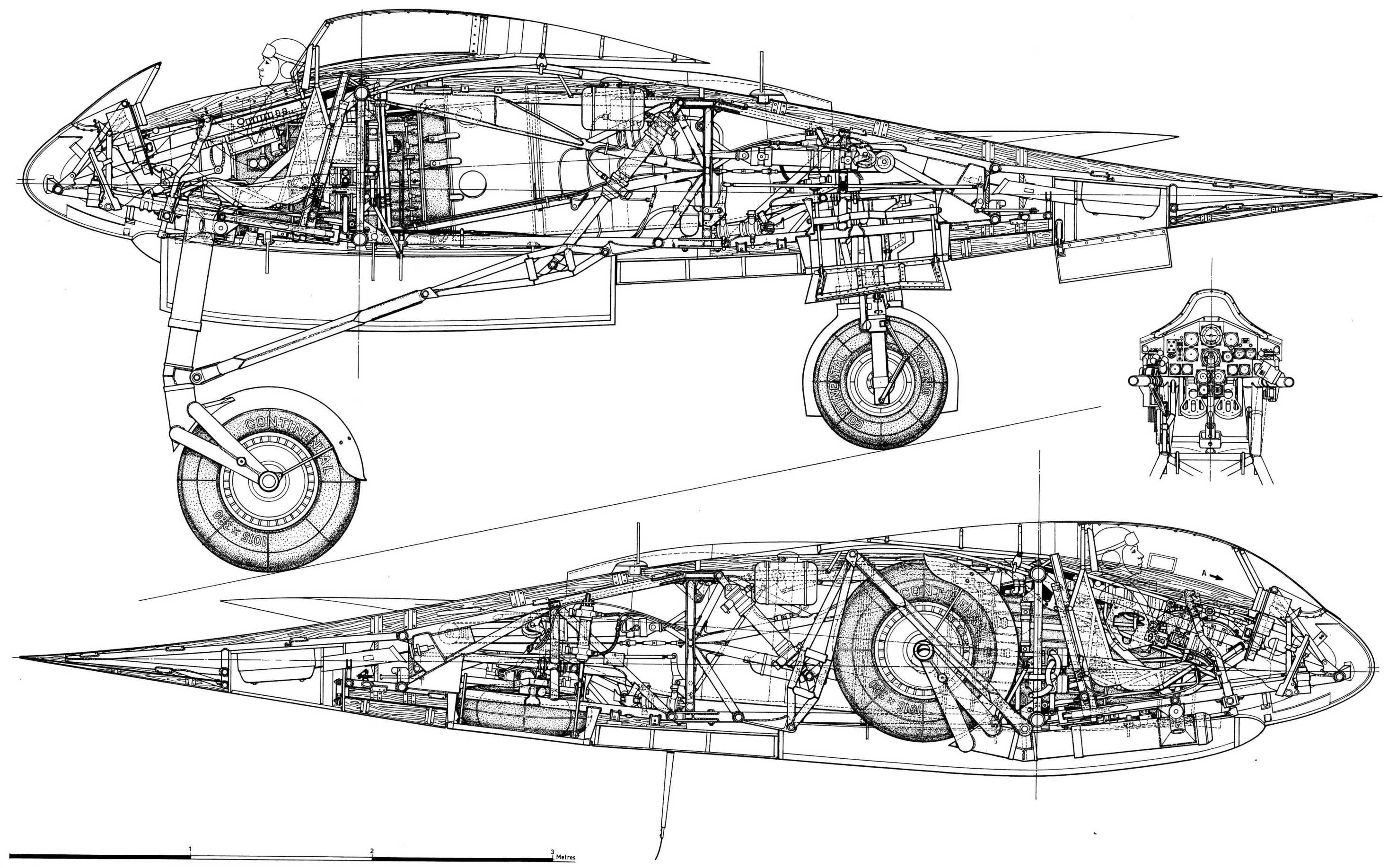
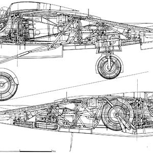
Wing structure comprised a main spar and one auxiliary spar or wooden construction with ply covering. The center section was built up from welded steel tube. Wing tips were all metal. The undercarriage was completely retractable and of tricycle type the front wheel folding backwards and the main wheels inwards. The nose wheel was castering and centered with a roller cam. When resting on the ground, wing incidence was 7° and the nose wheel took about 40% of the total weight.
Engine Installation
The jet engines were installed at -2° to the root chord and exhausted on the upper surface of the wing at 70% back from the nose (Fig. 22a & 22b). To protect the wings the surface was covered with metal plates aft of the jet pipe and cold air bled from the lower surface of the wing by a forward facing duct and introduced between the jet and the wing surface. The installation angle was such that in high speed flight the jest were parallel to the direction of flight.
General
The H IX was a single seat fighter bomber of 16 m span with twin jet engines, being a further development of the H V and H VII designs. Fig. 19 is a general arrangement drawing made from a wooden model found at Gottingen, where the first two of the type were built.
Four aircraft of the H IX type were started, designated V.1 to V.4. V.1 was the prototype, designed as a single seater with twin B.M.W. 003 jets, which were not ready when the airframe was finished. It was accordingly completed as a glider (Fig. 20) (not reproducible) and extensively test flown. D.V.L. instrumented it for special directional damping tests to determine its suitability as a gun platform. V.2 was completed (also at Gottingen) with two Juno 004 units and did 2-hours flying before crashing during a single engine landing. The pilot (Ziller) apparently landed short after misjudging his approach. V.3 was being built by Gotha at Friedrichsrodal as a prototype of the series production version. V.4 did not get beyond the project stage but was to be a two-seater night fighter with an extended nose to house the extra man (Fig. 19) (missing).
In shape, the H IX was a pure wing with increased chord at the center to give sufficient thickness to house the pilot and the jet units, which were placed close together on either side.
Aerodynamic Design
The H IX started as a private venture and the Hortens were very anxious to avoid failure so they avoided aerodynamic experiments wherever possible. A lower sweepback was used than on the H V and H VII and laminar flow wing sections were avoided as a potential source of trouble. Wing section at the junction with the center sections was 14% thick with maximum thickness at 30% and 1.8% zero Cmo camber line. At the centerline thickness was increased locally to 16% to house the crew. The tip section was symmetrical and 8% thick. Horten also believed that since the compressibility cosine correction to drag was based on the sweepback of the maximum thickness line, the ordinary section would show little disadvantage.
Wing twist was fixed by consideration of the critical Mach number of the underside of the tip section at top speed. This gave a maximum washout of 1.8°. Having fixed this, the CG was located to give trim at CL = 0.3 with elevons neutral. In deciding twist for high speed aircraft, CD values were considered in relation to local CL at operational top speed and altitude (10 km in the case of the H IX). Twist was arranged to give minimum overall drag consistent with trim requirements. The wing planform was designed to give a stall commencing at 0.3 to 0.4 of the semi-span.
Structure
Wing structure comprised a main spar and one auxiliary spar or wooden construction with ply covering. The center section was built up from welded steel tube. Wing tips were all metal. The undercarriage was completely retractable and of tricycle type the front wheel folding backwards and the main wheels inwards. The nose wheel was castering and centered with a roller cam. When resting on the ground, wing incidence was 7° and the nose wheel took about 40% of the total weight.
Engine Installation
The jet engines were installed at -2° to the root chord and exhausted on the upper surface of the wing at 70% back from the nose (Fig. 22a & 22b). To protect the wings the surface was covered with metal plates aft of the jet pipe and cold air bled from the lower surface of the wing by a forward facing duct and introduced between the jet and the wing surface. The installation angle was such that in high speed flight the jest were parallel to the direction of flight.