Bf 109F Throttle/Airscrew control mode switch interconnect? (1 Viewer)

Ad: This forum contains affiliate links to products on Amazon and eBay. More information in Terms and rules

gecko

Airman
42
4
Apr 18, 2014
Hi all,

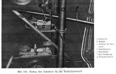
I am wondering if anyone knows anything about an interconnect device somewhere in the throttle control linkages which would automatically move the airscrew control mode switch below the throttle quadrant from manual to automatic when the throttle was pushed all the way forward. The device could be folded out of the way so as not to move the switch if the automatic airscrew control was malfunctioning, but otherwise it was left in place, presumably to prevent over-speeding the engine at full throttle if the blade pitch had been left too fine. It is mentioned in the Bf 109F Bedienungsvorschrift-Fl dated May 1941, but I have no drawing showing how it moved or what it looked like. I assume it is something similar to a moveable version of the striker plate on the early Spitfire throttle quadrants that bumped the landing gear indicator switch to the on position when the pilot moved the throttle forward if he had forgotten to turn the indicator on beforehand. Thanks for any help.
 
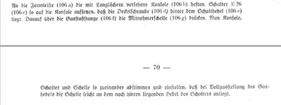
Managed to find something in a maintenance manual I forgot I had:
 

Attachments

  • throttle prop interconnect.jpg
    throttle prop interconnect.jpg
    57.5 KB · Views: 34
  • throttle prop interconnect2.jpg
    throttle prop interconnect2.jpg
    188.2 KB · Views: 34
Yes, good copy Gecko.
That switch does as you say. This is a bit of a peculiarity of the German VDM system. The box (switch) marked C on your pic is the AUTOMATIK ON/OFF switch. Feel free to ask any questions about this system, I am am an expert on this!

Eng
 
Many thanks, I do have a number of questions about this system! So while my initial question about item "g" in the above illustration is answered, I have a lot more! A friend is helping me with the translation of the Bf 109F Bedeinungsvorschrift-Fl, and so far the VDM system is the hardest part to understand. I have a grasp of the general idea of how it works, but the finer points are harder to understand. Following is from part of the pre-flight checks for the aicraft prior to starting the engine:

VDM-01.jpg

Switch on the circuit breaker of the mechanical-electrical VDM-automatic system (on the right cockpit sidepanel next to the rudder pedal) and the circuit breaker for the entire adjustment system (on the main distribution panel). Switch (below the throttle lever) on "Manual". Move middle thumb switch (on throttle lever) back and forth and then leave at 12 o'clock. Switch at "Automatic system ON", the screw must now run at 1 o'clock (valid only for DB 601 N). If the screw runs further, then the accumulator voltage is too low. If the accumulator cannot be replaced, then use the automatic system only in the air (at RPM over 1900).

Since electrical power is required to run the motor to change blade angle, why would it overshoot if voltage is too low? I would expect the opposite. The limitation for using the automatic system only above 1900 RPM makes sense if there are voltage problems, since the engine-driven generator is supplying electrical power above that rpm.

Here's another question, also about the automatic system overshooting. This is the section describing the use of the manual and automatic systems in flight:
VDM-02.jpg


Screw adjustment system (operation)
a) Generally, "automatic system ON".
At the start of a power dive by "pressing" and with quickly throttling up, impermissable overrevving of the engine is to be expected. Careful!
When idle-gliding with an indication of less than 200 kph the automatic system should be switched off (switch on the throttle lever) or take care not to exceed the final limit.
b) Economy flight (max. reach, barrier) by precisely keeping the RPM and boost pressure according to the range table through manual control.
Before diving, switch to "automatic system ON"
For feathering and with failure of the automatic system also set the screw manually.
c) When flying on manual adjustment with functioning automatic system, then the folding interlock must not be flipped up. With a malfunctioning automatic system, the interlock should be folded away.
d) If a dive is started with a switched-off automatic system, it is not allowed to switch to 'automatic' by giving full throttle at high speed, otherwise the engine will overrev.
e) When flying with manual adjustment, take care that the air screw is not set over 12 o'clock and further, for the limit is only at 1 o'clock. (For DB 601 N)

Once again, it seems as if the automatic system is capable of exceeding the limits of the propeller. It makes sense that with engine power at idle and at low airspeed, the automatic system is trying to maintain a minimum rpm, and thus reducing the blade angle as much as it can, but is there really no safeguard in the system to have it stop reducing blade angle automatically when the limit is reached? How far is the automatic system capable of reducing the blade angle beyond the limit? Is it also possible to exceed the limit in manual mode?

Lastly, a few related questions:

The manual consistently gives the clock limit for blade angle as 1 o'clock, but apparently only for the DB 601N. Do you know the limit for the 601E, or 601A?

What is the minimum rpm the automatic system will try to maintain? I know at max boost, it will maintain max rpm, and lesser rpm corresponding to lesser boost, but it seems there would have to be a point where a minimum rpm have to be maintained at boost settings lower than a certain limit.

Similarly, what input is the automatic system referencing when determining the correct rpm to maintain? I don't think it can reference boost pressure directly, since above full throttle height, boost pressure decreases even with the throttle lever full forward, and if the automatic system started reducing rpm in response, boost pressure would drop further, causing the system to further reduce rpm, and so on. Obviously that won't work. So is it referencing the physical position of the throttle lever or linkages somehow?

Assuming a high speed dive with a low power setting in automatic mode, the automatic system with be increasing blade angle to maintain the correct rpm. Is there a max angle the system will move the blades to, which upon reaching, will no longer be able to prevent rpm from rising?

How fast does the motor change blade angle?


Thanks for any insight you can give!
 
So, firstly to comment upon the description of the pitch indication "running too far " with low battery voltage. This description is thought to be a problem with interpretation or the technical writers understanding. As you probably know, the electrical pitch motor (EVG, 14501) is a reversible 24v electric motor with range of operation electrical contacts that cut the operation at a minimum (fine) setting and at a maximum (coarse) setting. Each end position disconnects the contacts for operation in that direction but leaves the contacts for operation in the opposite direction still available, if the selection the other way is made. This is to prevent the motor stopping forever at one end of travel! So, the electrical path is broken at the end of travel and the motor stops, in this case "1.00 O'clock". With low battery charge, the motor may not run all the way to the end stop before stalling and the electrical contacts may still be applying the low voltage/current although the motor is stalled. This is the condition that is described. Additionally, the switching of the power is done by relays and, they may fail to maintain good contact at low voltage. Also, some pitch indicators are electrical operation, that might have been an issue with indication at very low battery. In use, the system has no problem of "running past the limits" or "overunning at low battery".

Next point soon!

Eng
 
Here's another question, also about the automatic system overshooting. This is the section describing the use of the manual and automatic systems in flight:
View attachment 680664
Screw adjustment system (operation)
a) Generally, "automatic system ON".
At the start of a power dive by "pressing" and with quickly throttling up, impermissable overrevving of the engine is to be expected. Careful!
When idle-gliding with an indication of less than 200 kph the automatic system should be switched off (switch on the throttle lever) or take care not to exceed the final limit.
b) Economy flight (max. reach, barrier) by precisely keeping the RPM and boost pressure according to the range table through manual control.
Before diving, switch to "automatic system ON"
For feathering and with failure of the automatic system also set the screw manually.
c) When flying on manual adjustment with functioning automatic system, then the folding interlock must not be flipped up. With a malfunctioning automatic system, the interlock should be folded away.
d) If a dive is started with a switched-off automatic system, it is not allowed to switch to 'automatic' by giving full throttle at high speed, otherwise the engine will overrev.
e) When flying with manual adjustment, take care that the air screw is not set over 12 o'clock and further, for the limit is only at 1 o'clock. (For DB 601 N)


Once again, it seems as if the automatic system is capable of exceeding the limits of the propeller. It makes sense that with engine power at idle and at low airspeed, the automatic system is trying to maintain a minimum rpm, and thus reducing the blade angle as much as it can, but is there really no safeguard in the system to have it stop reducing blade angle automatically when the limit is reached? How far is the automatic system capable of reducing the blade angle beyond the limit? Is it also possible to exceed the limit in manual mode?

Here, we must comment upon language. These instructions often translate with quite blunt warnings about "limits" etc. I think that the general style is a little stern. Also, the descriptive terms used are often strange.
To note, this propeller control system in "AUTOMATIK" uses a simple cam controlled speeder-cup regulator for engine RPM. The regulator cam profile is designed to give a bias on the spring force in the regulator that gives a specific RPM versus the throttle position. There is no sensed link to Manifold Air Pressure MAP.
At low throttle position, the controlled RPM will be low and the combination of fast throttle movement with very steep dive could cause the engine to overrev.
The usual caution is given for flight where the propeller control system may be at or near its range of travel. This seems overstated, and they would rather that the pilot switch off the system "HAND" for low throttle, low airspeed descents. Also, there are cautions to avoid "limits", which in this case is probably the fine position cut-off.
Manual prop control was used for long-range flying with precise engine RPM/MAP. The caution to switch back to AUTO "before diving" is again curious, as it applies to all forms of flight after completing the range flying.
Item C. Again strange words, the word MUST is strange, especially as item D says you can't just use the interlock to select AUTO. They are mixing incomplete descriptions of how to manage the system with partial orders that do not cover all scenario's.
Item E basically does the same old caution of not setting too fine a blade pitch as you can easily overrev.. but it doesn't say that!
Your last two questions about "limits" should now be answered. The Automatik and Hand operations have the same theoretical range of blade pitch but, the function of the Automatic control is simply a product of the throttle lever position and actual engine speed.

Eng


Lastly, a few related questions:

The manual consistently gives the clock limit for blade angle as 1 o'clock, but apparently only for the DB 601N. Do you know the limit for the 601E, or 601A?

What is the minimum rpm the automatic system will try to maintain? I know at max boost, it will maintain max rpm, and lesser rpm corresponding to lesser boost, but it seems there would have to be a point where a minimum rpm have to be maintained at boost settings lower than a certain limit.

Similarly, what input is the automatic system referencing when determining the correct rpm to maintain? I don't think it can reference boost pressure directly, since above full throttle height, boost pressure decreases even with the throttle lever full forward, and if the automatic system started reducing rpm in response, boost pressure would drop further, causing the system to further reduce rpm, and so on. Obviously that won't work. So is it referencing the physical position of the throttle lever or linkages somehow?

Assuming a high speed dive with a low power setting in automatic mode, the automatic system with be increasing blade angle to maintain the correct rpm. Is there a max angle the system will move the blades to, which upon reaching, will no longer be able to prevent rpm from rising?

How fast does the motor change blade angle?


Thanks for any insight you can give!

Hi again,

The blade angle pitch limits are given for different aircraft, engines and propeller types. These are really the design range of movement. However, the figures given do have some tolerance and, there is a "fudge" factor for engines and propellers that perform slightly differently at the "12 o'clock" pitch setting for Take-Off, as a repaired or shortened prop will do. I am not sure what you need the figures for, but the Bf 109 fine pitch cut-off for the 601A/N would be about 1.00 o'clock, the E about 12.45. The actual setting figures are about 15min less but, that is the difference between the setting and what you get with a running system.
The minimum rpm speed in AUTO is about 1700, but the generator drops off line about 1900 rpm and the battery was small.
The rpm in AUTO is selected by throttle position and the throttle linkage to that cam on the regulator.
The max blade angle is very coarse, in fact it is feathered on the Bf 109 F-2, about 85 degrees at the 0.75 radius setting position.
The basic pitch change rate is 1.5 deg/sec

Cheers

Eng
 
Many thanks for your thorough replies, this is extremely helpful!

So, firstly to comment upon the description of the pitch indication "running too far " with low battery voltage. This description is thought to be a problem with interpretation or the technical writers understanding. As you probably know, the electrical pitch motor (EVG, 14501) is a reversible 24v electric motor with range of operation electrical contacts that cut the operation at a minimum (fine) setting and at a maximum (coarse) setting. Each end position disconnects the contacts for operation in that direction but leaves the contacts for operation in the opposite direction still available, if the selection the other way is made. This is to prevent the motor stopping forever at one end of travel! So, the electrical path is broken at the end of travel and the motor stops, in this case "1.00 O'clock". With low battery charge, the motor may not run all the way to the end stop before stalling and the electrical contacts may still be applying the low voltage/current although the motor is stalled. This is the condition that is described. Additionally, the switching of the power is done by relays and, they may fail to maintain good contact at low voltage. Also, some pitch indicators are electrical operation, that might have been an issue with indication at very low battery. In use, the system has no problem of "running past the limits" or "overunning at low battery".

Next point soon!

Eng

Ok, this makes sense and is more in line with how I thought it should work. Assuming a good battery, switching to AUTO with the engine stopped will cause the system to run the prop to full fine at 1 0'clock. If the battery is weak, there won't be enough power to get it all the way there.


Here, we must comment upon language. These instructions often translate with quite blunt warnings about "limits" etc. I think that the general style is a little stern. Also, the descriptive terms used are often strange.
To note, this propeller control system in "AUTOMATIK" uses a simple cam controlled speeder-cup regulator for engine RPM. The regulator cam profile is designed to give a bias on the spring force in the regulator that gives a specific RPM versus the throttle position. There is no sensed link to Manifold Air Pressure MAP.
At low throttle position, the controlled RPM will be low and the combination of fast throttle movement with very steep dive could cause the engine to overrev.
The usual caution is given for flight where the propeller control system may be at or near its range of travel. This seems overstated, and they would rather that the pilot switch off the system "HAND" for low throttle, low airspeed descents. Also, there are cautions to avoid "limits", which in this case is probably the fine position cut-off.
Manual prop control was used for long-range flying with precise engine RPM/MAP. The caution to switch back to AUTO "before diving" is again curious, as it applies to all forms of flight after completing the range flying.
Item C. Again strange words, the word MUST is strange, especially as item D says you can't just use the interlock to select AUTO. They are mixing incomplete descriptions of how to manage the system with partial orders that do not cover all scenario's.
Item E basically does the same old caution of not setting too fine a blade pitch as you can easily overrev.. but it doesn't say that!
Your last two questions about "limits" should now be answered. The Automatik and Hand operations have the same theoretical range of blade pitch but, the function of the Automatic control is simply a product of the throttle lever position and actual engine speed.

Eng

So I take it that the cautions to avoid the fine pitch limit are solely there to protect against overreving the engine during a power increase, and not a potential problem with the propeller system itself.

I understand item C to mean that they don't want you running at full throttle in manual mode if you have the ability to use automatic. The interconnect is a safety measure they don't want you to disable. It exists to save you from the worst consequences if you forget the proper procedure, and item D just tells you that it isn't part of the proper use of the system. Makes sense to me, though perhaps a strange way to put it.


Hi again,

The blade angle pitch limits are given for different aircraft, engines and propeller types. These are really the design range of movement. However, the figures given do have some tolerance and, there is a "fudge" factor for engines and propellers that perform slightly differently at the "12 o'clock" pitch setting for Take-Off, as a repaired or shortened prop will do. I am not sure what you need the figures for, but the Bf 109 fine pitch cut-off for the 601A/N would be about 1.00 o'clock, the E about 12.45. The actual setting figures are about 15min less but, that is the difference between the setting and what you get with a running system.

Can you clarify what you mean about the actual setting figures? Are you saying 15min this is the difference between factory fresh and a typical in service engine (e.g. new DB 601N running at 12:45 but one that has seen some wear and tear might be adjusted to 1:00), or is the difference between engine off and engine running?


The minimum rpm speed in AUTO is about 1700, but the generator drops off line about 1900 rpm and the battery was small.
The rpm in AUTO is selected by throttle position and the throttle linkage to that cam on the regulator.
The max blade angle is very coarse, in fact it is feathered on the Bf 109 F-2, about 85 degrees at the 0.75 radius setting position.
The basic pitch change rate is 1.5 deg/sec

Cheers

Eng

So, does 1700 rpm correspond to the idle setting of the throttle lever, or does everything less than some higher position of the lever yield a target rpm of 1700, and above that point a linear increase to max rpm at full throttle? Is 1700 rpm the standard minimum setting across all the DB variants, or is there some variation between different models?

How does governor mechanism compare to the hydraulically operated CSP systems on allied aircraft in terms of sensitivity and responsiveness? Will it hold RPM as precisely, with constant tiny adjustments, or will it wander a bit more? Assuming a responsibly fast throttle movement, is it more or less prone to overshoot the target rpm and yo-yo back and forth?

Is the 1.5 deg/sec speed the only speed that will be used, or will lesser voltage be supplied for a slower rate of change for smaller adjustments?

My purpose for all of this is building a computer simulation of the operation of the engine in various variants, starting with the DB 601N and E on the Bf 109F. I'm trying to get all the details right. Currently I'm working through the propeller, but the coolant, boost control, oil, supercharger, etc, etc are all on the list as the project progresses.

Once again, thanks for you help!

Dan
 
Hi Dan.

OK, if this a commercial or important project you can PM me for contact and detailed help on all those functions and also, my credentials. I am happy to help here and spread the word more generally.
First thing to say now is that this VDM Electric/mechanical system is quite good and well developed. It works nicely and accurately controls the 2,000bhp propeller power of a late Bf109.
Overall, its use in operation is generally as simple as a CSU with a separate speed control lever. However, it is rare now and very few people have experience with it. It is worth noting that the Allied reports about the system are mostly fair but, there are some mistakes in the write-ups and the more critical comments are over emphasised, as you would expect with enemy equipment.

The point about the battery is that the Bf 109 battery was small capacity, only about 5AH and it was common for the charge to be low. So, it is normal to be careful about using any electrical power until take-off as the generator only comes online at about 1900rpm. This is why it was normal to just test the prop system on preflight, not just turn it on AUTO and leave it on before start-up.

Because it is possible for the prop to be set at an inappropriate fine pitch by poor management of the system, over revving is possible in some circumstances. However, correct handling is not a problem for a competent operator. I would say that the text cautions are not well written. In fact, the DB engines are limited to 100% power setting with Manual prop control, Auto must be used above the 100% rpm/ata setting.

As regards the accuracy of the settings. The electrical drive functions at a high geared ratio, the motor runs-on after the manual switch is released or the end-of travel cut-off is reached, by about 10 min on the clock. This is not a functional problem.

In use, the Auto system reacts much as any CSU. In Auto, the governor has a sensitivity that is adjustable. This is usually set at 30 to 50rpm. This gives accurate speed control with no lag or wandering. In close formation flying there is only personal preference for Manual or Auto control, the advantages of Manual in this case are less wear and tear and less electrical load.

I will come back with the rest of your points a bit later.

Cheers

Eng
 
So, does 1700 rpm correspond to the idle setting of the throttle lever, or does everything less than some higher position of the lever yield a target rpm of 1700, and above that point a linear increase to max rpm at full throttle? Is 1700 rpm the standard minimum setting across all the DB variants, or is there some variation between different models?

How does governor mechanism compare to the hydraulically operated CSP systems on allied aircraft in terms of sensitivity and responsiveness? Will it hold RPM as precisely, with constant tiny adjustments, or will it wander a bit more? Assuming a responsibly fast throttle movement, is it more or less prone to overshoot the target rpm and yo-yo back and forth?

Is the 1.5 deg/sec speed the only speed that will be used, or will lesser voltage be supplied for a slower rate of change for smaller adjustments?

My purpose for all of this is building a computer simulation of the operation of the engine in various variants, starting with the DB 601N and E on the Bf 109F. I'm trying to get all the details right. Currently I'm working through the propeller, but the coolant, boost control, oil, supercharger, etc, etc are all on the list as the project progresses.

Once again, thanks for you help!

Dan

The integration of the Auto prop pitch and speed control with Throttle position is quite complicated, especially in dynamic conditions. However, I can cover the general points here and, the function is smooth in the real world.

We need to remember that the DB601/603/605 engines were designed to operate at defined rpm/ata in normal operation, eg 2100/1.05, 2300/1.15 etc. Also, the propeller was well matched to the power output. This means that if you set the prop in manual to give say 2100/1.05 and leave it there then open the throttle to give 1.15ata the rpm will rise to 2300 without changing the pitch. This is the same in Auto. The pitch has to change with Airspeed, so, as the speed rises and falls the pitch changes. If you start a climb as you increase Throttle and hold the same airspeed, the pitch remains the same. This is the same on ground testing. Manually set 12.00 O'clock gives all the rpm/ata figures, setting to Auto while doing this just stays the same pitch position if the system is correctly set-up.
So, in flight below say 2000 rpm in Auto, the system still maintains a related rpm (2000 in this case), but it is not a dedicated setting and ata will reduce also with Throttle. This continues down to 1700 rpm (the throttle position still signalling the controller for a balance of prop pitch that gives 1700 rpm) but, although the Throttle can close lower, the 1700 rpm is the lowest that the governor can be set by the linkage and if the Throttle is fully closed, 1700 is the figure you will get as the speed reduces, with very low ata, no power, and the pitch running lower (in effect prop air-braking). This is a very dynamic situation that is a bit like a CSU system with the prop speed set at 1700rpm lever setting as you reduce throttle and decelerate.
If you leave a 109 in Auto in flight and the Throttle fully closed, to say the Stall, the pitch will come back, possibly to 11.30 near the stall. On the ground in Auto, there is no airspeed to keep the rpm at 1700 and the pitch will come right back to the Fine pitch limit (the "1.00 O'clock" cut-off) with a closed throttle and about 450rpm slow-idle.
As covered above, the pitch movement does not overswing, the max rate it can move is 1.5 degrees/sec (15min on the clock). RPM overswings are possible if the prop is set manually at a fine pitch that is well below the speed related pitch, and the throttle opened wide. The pitch rate is lower than hydraulic CSU but, the VDM system works well for full Aerobatic and combat flight, the cautions are for sudden power-dives from low airspeed and from incorrect handling using Manual control.
The system works at 1.5 degrees a second and although it would be worse on a low battery, it is normally used at system voltage with the generator online.

Eng
 
Oh yes, forgot! The 1700 rpm Auto min rpm seems to be standard, but I have a reference for 1900 rpm on the Bf 110 G with the DB 605 B. The difference here is the different reduction ratio of the DB 605 B engine that gives a higher crankshaft speed compared to the propeller shaft speed. Although the control cam of the governor is different, the functional parts of the system and governor are the same as the DB 605 A.
Eng
 
Last edited:
Hi Dan,
I hope that the info is useful. There is still a lot more detail about this VDM system etc, but you needed to get the basics of it straight. So, I hope that is a good start. Can you give me an email contact for more specifics?
Cheers

Eng
 

Users who are viewing this thread

Back