DB603/605 - different compression ratio at left and right cylinder blocks (1 Viewer)

Ad: This forum contains affiliate links to products on Amazon and eBay. More information in Terms and rules

seesul

Senior Master Sergeant
Hello to all,

I haven´t been here for a long time so first of all, greetings to all old wulfs :)

Anyway, a member of one czech forum asked and interesting question and I haven´t found any clear answer yet.

Why does DB603/605 have a different compression ratio at the left and right cylinder blocks? 7,5:1 left cylinder bank and 7,3:1 right cylinder bank. I got this info from Wiki. Should it be vice versa I´d think it could be a compensation of the pressure drop related to the left side mounted compressor but if is true what Wiki says I got no clue.

And also, interesting is that DB601 had the same CR for all the cylinders...

I´ve found something here Daimler Benz DB 603 Engine Compression Ratios. - PPRuNe Forums but I´m still not convinced about the clear answer.

Can anyone help?

Thank you!

Roman
 
Last edited:
It won´t be easy for me to translate it but I can try it...

Because of engine turning direction, compressor placing and timing of valve overlap the filling ratio of one cylinder bank was different to the other cylinder bank. So at DB603 and DB 605 it was compensated by a different compression ratio. DB 601 didn´t have such a big valve overlap, that´s why it had the same compression ratio for all the cylinders.

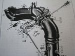
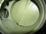
And as for why the cylinderbank closer to the compressor had higher compression ratio - it was because of the shape of the throttle flange, that, despite of the fact, that the suction manifold was longer, provided the higher filling grade of the right cylinder bank. There´s a small throttle at the attached pics that cooperated with the big throttle while the small throttle had a small own chanell responsible first of all for a idle. The system was necessary just because of big valve overlap as without it the idle wouldn´t work reliably.

It´s a translation of Hilmar´s explanation from here http://www.luftwaffe-bullet-board.com/viewtopic.php?p=107190#107190
Just let me know if you got the meaning :)
 

Attachments

  • drosselklappe_603_508.jpg
    drosselklappe_603_508.jpg
    114.9 KB · Views: 263
  • drosselklappe_innen_205.jpg
    drosselklappe_innen_205.jpg
    52.5 KB · Views: 249
Last edited:
Yep, that sums it up; in a slightly easier to read or comprehend in English.., and the why is because of the motor cannon requirement in the design.

The supercharger outlet to the intake manifold(s) was not designed with a central/equal split for left and right banks because that space was needed for the hub weapon, so the supercharger was mounted on the left port side, with the inertia starting gear directly opposite.
Since the charger was on the left, the manifold was now asymmetric and this caused many problems until they (Mercededes/DB) sorted it out via some methods to fool the charged intake to 'thinking'/acting as if it was equal and symmetrical.

To compensate for the greater efficiency of filling the left banks closer to the superchargers outlet side, the right bank comp' ratio was lowered to equalise the speed and pressure differences between the un-equal left and right bank intake manifolds.

Certainly the more air you have to pump into the cylinders at higher piston speeds, the more cylinders in the engine you'd wish to be closer to each other on performance and attributes, especially when the intake system when connected to after a supercharger should be thought akin to a force fed trumpet or clarinet etc.

So as to not create problems like rough running, unequal idling, throttling up misfires etc, this could also lead to extra mechanical problems and possibilities of faults, failures or engine damage specifically if/when it combines with harmonic fluctuation ranges that could break a bearing or a web within the engine casing if it got out of hand.

I hypothersise that it could likely that the internal diameters, dimensions tapering details if any are also different enough between the left and right manifolds sections. Apart from their actual lengths this would create a equal induced length within each side of manifold system IMHO.

I understand the theory, but failed the math - thermodynamics was ( is) a fun subject, if just for the theory side....
 
Last edited:
It always makes me wonder when I´am thinking of the technical solutions from late 30´s and early 40´s...
They were so far with the development that sometimes it´s not easy to understand the solution even today...in a age of electronic control units and CAN bus...
 
It always makes me wonder when I´am thinking of the technical solutions from late 30´s and early 40´s...
They were so far with the development that sometimes it´s not easy to understand the solution even today...in a age of electronic control units and CAN bus...

jeez...double posting...sorry...
 

Users who are viewing this thread

Back