FW-190 D9

Ad: This forum contains affiliate links to products on Amazon and eBay. More information in Terms and rules

courtjester140

Recruit
8
0
Nov 23, 2008
Hello,
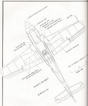
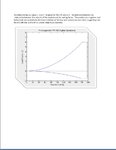
I'm doing a report for my aircraft structures class on the FW-190 d9. I'm specifically analyzing the wing structure. I seem to be missing some information however. I've found Soren's post quite a while back to be quite useful (comparing the 190 to a p-51), but i need the root and tip chords of the wings, as well as the wing sweep at the quarter chord. Also, the locations of the mounted machine guns along the span of the wing would be useful in load calculations. Basically i'll need information to construct a rough V-n diagram (so I'll also need max and min load factors).

If you guys have this information it would be incredibly helpful. And also if anyone is interested in a dogfight i frequent il-2 on hyperlobby as courtjester140:D

Thanks!!!


EDIT:
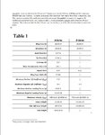
Considering the seemingly unavailability of information regarding this plane, I've decided to combine information about both this plane and the A-8 version (of which more information is readily available). Since the wing geometries are pretty much identical, the numbers should end up being pretty similar for either aircraft. Normally I wouldn't do something as stupid as this, but my professor says that its alright considering the lack of information I have, and that the process of analyzing what I know is more important.

once again, thanks!
 
Cool what degree are you working on?

I am taking classes through Embry Riddle right now for a B.S. in Aviation Maint. Management. They gave me half the credits already because I have an A&P.
 
suggest purchasing some books for your research like most of us have. JaPo and Eagle Editions have volumes covering the D-9 including Schiffer pubs on the east coast

do a book search on google
 
Hi Courtjester,

>I've decided to combine information about both this plane and the A-8 version (of which more information is readily available). Since the wing geometries are pretty much identical, the numbers should end up being pretty similar for either aircraft. Normally I wouldn't do something as stupid as this, but my professor says that its alright considering the lack of information I have, and that the process of analyzing what I know is more important.

Hm, as far as I know, the wings were actually identical, so it doesn't seem even remotely stupid to me to substitute one for the other ...

If you feel like it, please post your results here - I imagine that would be quite interesting for the Focke-Wulf fans on this forum! :)

Regards,

Henning (HoHun)
 
I'm studying Aeronautical Engineering here. I actually almost went to embry riddle in arizona, but decided i like cold weather over hot weather, so here i am :lol:

as far as books, as a typical college student I have absolutely no money. Our library had several editions of "Jane's All the World's Aircraft" but none of them from WWII era included anything german (americans being babies about Germany starting a war and excluding them?)

But anyway, I'll be sure to post my results here when I finish the report.
 
Maybe some of this will help. From the book History of German aviation Kurt tank Focke Wulfs designer and test pilot by Wolfgang Wagner
 

Attachments

  • fw-190d.pdf
    251.9 KB · Views: 235
Best Ive found of a scale drawing of a F-190D. This one from the book Yellow 10, Fw-190D-13 by eagle files publishing.
 

Attachments

  • fw.JPG
    fw.JPG
    79.5 KB · Views: 218
Well, the only data that is important that I am missing is the maximum and minimum loading factors as well as the maximum dynamic pressure. What I will most likely end up doing is taking values of those from a similarly sized WWII warbird such as an ME109, or a P-51, or a spitfire. The accuracy of this report will be diminished but not by much, I'll be sure to make note of the sources of all numerical constants somewhere in the report.
 
Hi Courtjester,

>Well, the only data that is important that I am missing is the maximum and minimum loading factors as well as the maximum dynamic pressure.

I have a translated Focke-Wulf data sheet here that reads:

"Structural strength: For Fw 190A-8/R2 on fighter operations, at G = 4450 kg, safe 'G' factor nA = 6,0"

"On fighter-bomber operations, at G = 4775 kg, nA = 5,5"

nA obviously is the German "sicheres Abfanglastvielfaches" ('safe pull-out load multiple'), but unfortunately I don't know the exact definition of this regarding safety factor, possible asymmetric loading and influence of airspeed (which I suspect, from some figures I've seen).

The translated manual that is the source of the data sheet can be downloaded here:

Focke Wulf Fw-190

The data sheet is on page 114 according to Acrobat Reader's count.

Regards,

Henning (HoHun)
 
Hi Courtjester,

>

The translated manual that is the source of the data sheet can be downloaded here:

Focke Wulf Fw-190

The data sheet is on page 114 according to Acrobat Reader's count.

Regards,

Henning (HoHun)


that was an amazing read. Where did you find it?:shock:
 
Hi Courtjester,

>that was an amazing read. Where did you find it?:shock:

I sense a misunderstanding ... I found it on the site I referenced :)

The site is run by a fellow forum member, Ron Handgraaf, who has a great collection of manuals which he generously shares with us.

No idea where he finds them, but I'm very glad he does!

Regards,

Henning (HoHun)

Ah, i meant where did you find the website, poor choice of wording on my behalf. The loading factors are extremely useful. For this report however I will use the highest value given, for a worst case scenario sort of thing. Everything will be maximum. I'm writing the introduction for this report now, so once its completed (hopefully by the end of the night, of course for me the end of the night is around 2 am8) ), i will post it in this thread. Feel free to rip it to shreads.
 
I apologize for the long wait. I haven't had much time to work on this since thanksgiving:( . I've basically got a rough introduction finished, and a little sneak peak of the next section, which will include force calculations along the wingspan. And a question, should I include something about Kurt Tank in the introduction? He seems worth mentioning.

EDIT: sorry about that thing that says "the packet" in bold, i couldn't find the packet where i got that information from, so i couldn't properly cite it, thats why i left it bold so that i could go back and fix it. its from an aerodynamics book.
 

Attachments

  • report1.JPG
    report1.JPG
    169.3 KB · Views: 144
  • report2.JPG
    report2.JPG
    81.5 KB · Views: 143
  • report3.JPG
    report3.JPG
    42.5 KB · Views: 145
Although I haven't read it fully yet, your paper looks good so far. No doubt those with more knowledge/experience of the relevant technical content will provide suitable comment/critique.
As a courtesy, and a matter of 'form', it is generally accepted that the designer, in this case Kurt Tank, should be acknowledged in this type of work, preferably with his status (eg DiplEng), and normally in the opening statements within, if possible, the introduction. A suitable example, reference your paper, could read " .....designed by Kurt Tank (etc) and developed by..."
I hope this observation is useful, and well done.
Good luck,
Terry.
 
Hi Courtjester,

>I've basically got a rough introduction finished, and a little sneak peak of the next section, which will include force calculations along the wingspan.

A promising beginning! :)

One detail I noticed concerns the fuel tanks ... 525 L was the standard fuel capacity of the early A series, but with the A-8, it became possible to install another 115 L fuel tank aft of the cockpit for a total of 640 L of fuel. I think this extra tank was standard on the Fw 190D-9.

The entire fuel load of the Fw 190 was carried within the fuselage, unless we're talking about drop tanks on the wings, which were rarely used (a single drop tank below the fuselage was the common installation). Only the Fw 190-derivative Ta 152 featured wing tanks.

Regards,

Henning (HoHun)
 
thanks for the feedback! I wasn't aware that all of the fuel was contained in the fuselage. However, for the sake of demonstrating our skills at analysis, i'm going to leave it as it is, but make a note that all of the fuel is contained within the fuselage. I'm going to be making many assumptions like this, by request of my professor. For example, for calculating the thickness of the wing skin and spar webs, we are using a 2 cell wing box, when the 190 actually was a single cell wing box. If you guys want, over my winter break I can revise all of these assumptions and create a more accurate report.
 

Users who are viewing this thread

Back