Hs 123 A-1, "Red T"10./Lg 2; Greece April, 1941 Group Build

Ad: This forum contains affiliate links to products on Amazon and eBay. More information in Terms and rules

kgambit

Tech Sergeant
1,719
2
May 29, 2006
North Carolina
Decided to do a second build for the MTO Group build:

Hs123_in_greece3.jpg


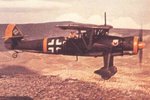
(Note that the caption in the picture describes the victory tally markings as a Werknumber! :LOL: )

Color scheme is as follows:

Cockpit interior: RLM 02
Upper surfaces and fueslage: RLM 70
Lower surfaces: RLM 65
Engine cowling, rudder, and lower wing tips: RLM 04
Markings: Black Triangle w/ white border, red "T", Infantry support badge (I know there's another name for it but my mind is turning a blank at the moment)

Here's a shot of the real plane and the squadron it was attached to.

Hs123_in_greece2.jpg


You can clearly see the lower wing tips are lighter than the surrounding wing in the preceding pic ( if not copy the pic and boost the contrast ).

Hs123_in_greece1.jpg


The kit is the Airfix 1/72 scale.

Given the small size of the cockpit interior I'm debating how much to do to it but I will do the following:

1) Scavenge an instrument panel from the few spares that I have - (done)
2) Build the forward cockpit bulkhead from plastic card (done)
3) Fabricate a control yoke since the kit doesn't come with one (done) and run a bit of painted fishing line to the rear of the plane to simulate the control cables
4) Create a new head rest - the head rest should actually be triangular, not round - (done)
4) Sand off all of the rivets on the rear wings, tail and fuselage (done)
5) Add PE seat belts
6) Create Traingular shaped brace in the front engine cowling (done)


I'm still debating whether to do any of the following:

a) display the cockpits "doors" in the down position - (that means cutting away part of the upper fuselage and building new doors - it's also the ONLY way to see anything inside the cockpit.
b) add the oxygen tank / oxygen unit to the starboard cabin side (in progress but not sure I will add it in)
c) add PE rudder pedals
d) add some controls to port side of cabin
e) add internal ribbing

Here's a couple of shots of the interior:

20.jpg


File0178.jpg


Hs123_cockpit5.jpg


Hs123_cp06.jpg


I have a ton of great detail shots - if anyone is interested, I'll post the rest. :D

Kit is actually well underway, but my darn camera is down for maintenance. Here's a very early shot of the progress (before Evan convinced me that I should definitely remove the rivets - something about them looking like 'balls on a dog' was the line that did it. :LOL: ) Actually, the entire engine cowling is finished and can just be added on, the rivets are all off, and the cockpit work is about 60% done

IMG_0021.jpg


Only problem I am having so far is the darn decals on this kit are ANCIENT. I'm not sure they are salvageable.
 
Last edited:
Yep, my bad, I posted it on the other! Sorry, hows the model though?

Lots of little detail work in the cockpit in progress.

Here's the updated status:

Finished:

01 ) Scavenge and paint an instrument panel from the few spares that I have
02 ) Build the forward cockpit bulkhead from plastic card
03 ) Fabricate a control yoke since the kit doesn't come with one
04 ) Create a new head rest - the head rest should actually be triangular, not round - will be glued in after the fuselage halves are mated
05 ) Create Triangular shaped brace in the front engine cowling
06 ) Add PE seat belts
07 ) Drill out holes for new gun barrels
08 ) Cut gun barrels from hypodermic tubing - Note: the Hs 123 frequently had a field modification that replaced the 2× 7.92 mm MG 17 machine guns with 2× 20 mm MG FF cannon and that's what I am going to try to replicate
09 ) Drill a hole in the rear cabin bulkhead for control yoke cabling.


In progress:

10 ) Sand off all of the rivets on the rear wings, tail and fuselage (nearly done) - there are a LOT of rivets on this kit - a bl**dy lot of rivets!
11 ) Drill holes in underside of upper wing and matching holes in center of fuselage between gun channels for strut cabling. Cables will be 0.006 inch brass railroad wire
12 ) Fabricate new cockpit doors to display the cockpits "doors" in the down position - (that means cutting away part of the upper fuselage and building new doors - it's also the ONLY way to see anything inside the cockpit.
13 ) Add the flooring forward of the front cabin bulkhead - this isn't going to be really visible but I need it as an anchor point for bottom portion of the control yoke - once I see what this entails I MAY add PE rudder pedals - but they are going to be REALLY hard to see so I might leave them out
14 ) Add internal ribbing - I am going to use a set of PE sidepanels that I scrounged from an Airwaves PE set for another kit. Somebody is always selling PE sets at bargain prices so I tend to buy them even though I don't have the specific kits they are intended for. I need to cut the side panels down and remove some extraneous bits
15 ) Add port side control levels and possibly add the small instrument panel there as well
16 ) Attach cable to bottom of control yoke and run cable from control yoke thru rear bulkhead - I'm going to use 0.008 inch diameter (0.2mm) 4 lb monofilament test line - that scales to 0.56 inches (14.4 mm) at true scale - that's about right for a cable I think - possibly a bit thick but it's the smallest I could get. - I might be able to scrounge some 0.006 inch railroad wire (that scales up to 0.43 inches or 11 mm) but I'm not sure it's THAT critical.

LOTS to do still.

Canceled:
17 ) Finish the oxygen tank / oxygen unit to the starboard cabin side
a ) the oxygen tank is finished and was built from 1 mm and 0.5 mm evergreen tubing which were butt end mated and then sanded to get the proper shape
b ) the frame for the unit is nearly finished. It was built from 0.010 " plasti-card with holes drilled out as in the image in the first post. I've rolled it from end to end so that it has nearly the right oval cross section as seen from top down. The plasticard wants to revert to its flat shape so it's going to be tricky getting this shaped properly. Once the oxygen regulator is ready, gluing it into the fram will help.
c ) the second tank inside the frame which I believe is the oxygen regulator has been built - again from 1 mm and 0,5 mm evergreen tubing. I need to run lines from the tank to the regulator and from the regulator to the "mask" - those will be built from the fishing line

Bottom line is that there just isn't enough room to squeeze this into the cockpit. I did a test fit with the oxygen tank and the seat in place and the oxygen regulator unit is just not going to fit. The ovygen tank is a tight fit without anything else but the rgulator unit is comprised of a tank and a frame and the combination is just a bit too big. I'm looking at some way to alter the design to make everything fit.


I'll add some new pics possibly later this week or next. A lot of this stuff won't be interesting until it's painted and installed - it's simply tiny, but I'll see what I can do.

Note: I'm worried that I am biting off more than I can chew with all this, so I reserve the right to revise this list. :lol:

Decals might be an issue with this kit as well. Evan was kind enough to send me a bunch but I won't know if what I have is going to do the job. The decals I had from the kit were in just miserable shape!
 
Last edited:
Two shots showing what is going to be added to the interior and some other details:

IMG_0103v2.jpg


IMG_0105v3.jpg


The shots were taken in a hurry so they are a little out of focus.

They show from left to right ( in the forground)

Prop and engine cowling with the engine braces (the braces need to be redone - they were very flexible and all the rough fitting just knackered them up - plus I need to reposition one of them, it's slightly out of whack)

New gun barrels and the wire struts just in front - the wire struts shown are 0.008" fishing line - I may use railroad wire instead.

Rear bulkhead (kit part) and behind it is the pilots seat with PE belts installed

Forward bulkhead - scratch built - with the instrument panel I took from spare parts
next to that is the flooring in front of front bulkhead (the area with the notchs needs to be trimmed down a bit )

Lower portion of control yoke (scratch built) with the control yoke pivot arm in place but not glued (the pivot arm extends under the flooring to the front of the plane) - to the right of it is a second control yoke showing the cable running thru it (that's a 0.006" railroad wire)

Just above that is the upper part of the control yoke - scratch built by wrapping evergreen rod in a oval coil and then CA'ing it onto itself and sanding it back into shape. That single piece took five tries to get right.

Above the upper part of the control yoke are the oxygen unit frame, the oxygen unit and the oxygen tank painted blue. The oxygen tank needs to have some scrap PE strapping added as well as a line running to the oxygen regulator - the unpainted cylinder. The frame (with the holes drilled into it) is slightly overiszed and will need to be trimmed down a bit more. Putting into place is going to be fun, as the frame has to be wrapped around itself into an oval and then glued together and then to the interior side wall.

To the extreme right are the 4 x 50 kg bombs - two are painted as general purpose bombs (yellow stripes) and 2 are incendiary. The incendiary bombs need to have the back part of the bomb painted red. I have two versions of this kit, and I am going to repaint the bombs in something closer to RLM 02. They just look a little dark to me.

In front of them is the fuel tank with the mounting straps painted.

At the far back are the two fuselage halves showing the PE side panels that will be added to simulate the interior ribbing. They are not glued in and just shown to give you an idea of what will be added. The upper rib will be flush with the lip of the door opening and the hanging cross ribs will be flush with the back mounting flange for the rear bulkhead.

I think that's everything. :D
 
Last edited:
Looking good. Seems like a lot of detail work going in there.
In the second pic, is that under artificial light? If so, can you adjust the 'white balance', as the colour cast detracts somewhat. If it's the flash, try changing to available light. Not a problem at the moment, but it could affect the 'finished' shots, used for judging, if the colour cast is present. Would hate to see you possibly lose points because the judges thought the colour scheme was weird!!

IIRC, the first pic was taken with both flash and artificial light and the second was just the flash. I'm going to have to get my hands on my wifes' Ot-light when I do the final pics. :D

I redid the second pic, is this better?

IMG_0105v3.jpg


And yeah, that's a TINY space inside that cockpit too. :lol:
 

Users who are viewing this thread

Back