A couple of months ago, with a coincident, I found a method to form rivet heads on model kit's exterior surfaces.
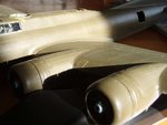
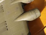
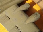
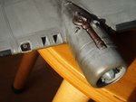
I have been on a Monogram/Hasegawa B-17G for more than two years but it was held up due to the kit's exterior was way too "clean." As can be seen from actual a/c photos, the surface of the B-17 is surprisingly roughened with numerous rivet heads planted on the flat sheet metal. Since I couldn't find any good way to re-create the rivet heads on the kit at that time, I have been away from the project for more than a year, and had started another project, the A-36A in 1/32 scale, build from scratch. I needed some of rivet heads be formed even on the Mustang's surface, though not as many as on the B-17.
The method I found is as follows;
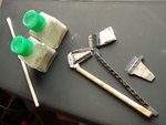
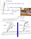
1) make liquid stylene plastic, by mixing pieces of plastic material with solvent type plastic kit glue such as Liquidpoly from Airfix or one of the Tamiya Cements. In my case Tamiya's white plastic sheets were used to make the special mix.
2) make an own "rivet tool" or two by closely lining up the sawing needles on a small piece of flat plate. The needles are then fixed with superglues. Be sure that the end of the needles are lined up on an arch with the radius of 2 to 2.5 inches. I made one when I made the Lancaster but used it quite differently.
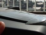
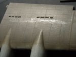
3) prepare the surface of the wings, fuselage and other parts by wet sanding with #320 sandpaper. You can scribe not only on the panel lines but also for accentuating the lap joints of the sheet metal on the real planes.
4) draw rivet lines on the surface using pencils. This should be done carefully. The work should be started from a small area and then proceeded step by step.
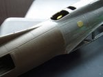
5) apply the mix generously onto the surface with a flat brush and wait for about 20-30 minutes. You will have not so rough surface for brush application, after drying for that length of time. Be careful not to leave your fingerprints on the half-dried surface. I used a pair of latex medical grove here.
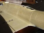
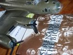
6) you can see the lines drawn on step no.4. Then use the rivet tool to create rivet heads by slightly digging up on the softened surfaces. For this the tool can be tilted somewhat.
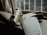
7) If a certain area (entire fuselage or wings) was finished, I recommend to paint them to the base color at this step. This enables to grasp the texture of the working at early stages and can be used to adjust, touching up or to re-working on that area. Also, handling of the model on the steps thereafter will result in a certain half-grossy condition on the painted surface. Actually this is a result of holding by human hands and fingers.
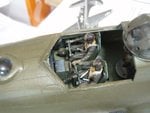
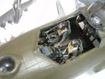
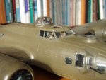
8) In my case of the B-17 "The Leper Colony," the wings, the tailplanes and the fuselage are all removable. Also the control surfaces are cut and corrected.
I exhibisited this hastily finished model at JMC Contest run by Hasegawa held early this month in Tokyo8).
I have been on a Monogram/Hasegawa B-17G for more than two years but it was held up due to the kit's exterior was way too "clean." As can be seen from actual a/c photos, the surface of the B-17 is surprisingly roughened with numerous rivet heads planted on the flat sheet metal. Since I couldn't find any good way to re-create the rivet heads on the kit at that time, I have been away from the project for more than a year, and had started another project, the A-36A in 1/32 scale, build from scratch. I needed some of rivet heads be formed even on the Mustang's surface, though not as many as on the B-17.
The method I found is as follows;
1) make liquid stylene plastic, by mixing pieces of plastic material with solvent type plastic kit glue such as Liquidpoly from Airfix or one of the Tamiya Cements. In my case Tamiya's white plastic sheets were used to make the special mix.
2) make an own "rivet tool" or two by closely lining up the sawing needles on a small piece of flat plate. The needles are then fixed with superglues. Be sure that the end of the needles are lined up on an arch with the radius of 2 to 2.5 inches. I made one when I made the Lancaster but used it quite differently.
3) prepare the surface of the wings, fuselage and other parts by wet sanding with #320 sandpaper. You can scribe not only on the panel lines but also for accentuating the lap joints of the sheet metal on the real planes.
4) draw rivet lines on the surface using pencils. This should be done carefully. The work should be started from a small area and then proceeded step by step.
5) apply the mix generously onto the surface with a flat brush and wait for about 20-30 minutes. You will have not so rough surface for brush application, after drying for that length of time. Be careful not to leave your fingerprints on the half-dried surface. I used a pair of latex medical grove here.
6) you can see the lines drawn on step no.4. Then use the rivet tool to create rivet heads by slightly digging up on the softened surfaces. For this the tool can be tilted somewhat.
7) If a certain area (entire fuselage or wings) was finished, I recommend to paint them to the base color at this step. This enables to grasp the texture of the working at early stages and can be used to adjust, touching up or to re-working on that area. Also, handling of the model on the steps thereafter will result in a certain half-grossy condition on the painted surface. Actually this is a result of holding by human hands and fingers.
8) In my case of the B-17 "The Leper Colony," the wings, the tailplanes and the fuselage are all removable. Also the control surfaces are cut and corrected.
I exhibisited this hastily finished model at JMC Contest run by Hasegawa held early this month in Tokyo8).


")