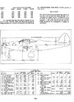
Mid-Engine layout

Ad: This forum contains affiliate links to products on Amazon and eBay. More information in Terms and rules

One thing RAF pilots were decidedly unimpressed with was the thought of half a ton of engine, poised behind their kidneys, and liable to break free in a forced landing.

I wonder how much of this is just illogical psychology, afterall half a ton of engine in front of you poised to break free and crush you from the other direction in a forced landing is hardly a much better prospect.
Still, if the RAF guys expected to fly them didn't like them then it's no surprise they didn't see much service in the RAF.
The Russians apparantly loved them (and the more powerful King Cobra version too).

.....those long driveshafts, weren't there stories of balance vibration issues with that sort of installation?
(personally it'd be the thought of going into combat with one of those doing a couple of hundred/thousand RPMs between my legs that gave me the heebee-geebees, one lucky/unlucky hit starting it to go off balance out of shape would not be the stuff for the making of a pleasant day!)
 
Last edited:
"I would think that two separate engines could not be mounted as close together as the V-3420 halves were, because engine mounts would have to be fitted between the two engines and access to them would be required - making the installation wider."

You don't have 2 seperate engines mounted together, it's all ONE block!!!
 
Common crankcases, very neat.
I wonder how come Daimler Benz didn't explore that idea with the DB606/610/613?
It would seem to offer a much better solution to the various routing ancilliary problems their double engines faced.
I suppose the DB604 was heading this way before cancellation.
 
Last edited:
It may be one crankcase but the real point is that the P-75 had to be 5 feet wide to hold it instead of 2 1/2 feet wide like the P-39. Since the P-75 was rather round in cross section rather than a flatten oval that meant even more volume. Given a few feet between the engine and the cockpit and there is room for a fair amount of fuel in the fuselage over the CG. Room the P-39 did not have.
As point about re-engining the P-39. While the engine was close to the center of gravity the CG of the engine was not on the CG of the aircraft so adding 100-200lbs on the aft end of the engine is going to mean 100-200lbs several feet away from the CG. In fact the nose of the engine was just aft of the CG of the aircraft. See:

http://www.zenoswarbirdvideos.com/Images/P-39/P39WBC.pdf

CG is under the aft edge of the door.

Perhaps a different engine could be used but it is going to require a whole lot of engineering time. Please look at the P-63, the cockpit is now ahead of the wing instead of just over the leading edge. While the fuselage was lengthened 2 feet the wing was NOT left in the original position but moved aft.
 
It may be one crankcase but the real point is that the P-75 had to be 5 feet wide to hold it instead of 2 1/2 feet wide like the P-39. Since the P-75 was rather round in cross section rather than a flatten oval that meant even more volume. Given a few feet between the engine and the cockpit and there is room for a fair amount of fuel in the fuselage over the CG. Room the P-39 did not have.
As point about re-engining the P-39. While the engine was close to the center of gravity the CG of the engine was not on the CG of the aircraft so adding 100-200lbs on the aft end of the engine is going to mean 100-200lbs several feet away from the CG. In fact the nose of the engine was just aft of the CG of the aircraft. See:

http://www.zenoswarbirdvideos.com/Images/P-39/P39WBC.pdf

CG is under the aft edge of the door.
Perhaps a different engine could be used but it is going to require a whole lot of engineering time. Please look at the P-63, the cockpit is now ahead of the wing instead of just over the leading edge. While the fuselage was lengthened 2 feet the wing was NOT left in the original position but moved aft.

Actually the P-39 (and I would assume the P-63 had two CG envelopes to deal with.
 

Attachments

  • p39.jpg
    p39.jpg
    120.9 KB · Views: 111
I would imagine that most, if not all, tricycle gear aircraft had a CG that shifted as the gear came up. Actually even some tail draggers could, P-35s and Fairly battles come to mind. Anything where the wheels moved for and aft as they retracted instead of in line with the CG. Or are you referring to the vertical position of the CG?

Correct me if I am wrong but isn't a forward CG easier to deal with than an aft CG? at least within some sort of reasonable limits?

Most if not all tricycle retractable gear aircraft had a change in C/G, MAC when the gear was retracted. What was unique with the P-39 was you were watching a C/G envelope on the vertical axis as well as the longitudinal axis, not very common in aircraft. You do find this in helicopters.

Forward C/G provides better controllability and spin characteristics, a rear C/G tends to give the aircraft a little more speed.
 
RLM limited DB601 engine production, cancelled funding for the DB603 followed by cancellation of funding for the DB604. That pretty well wrecked the relationship between Daimler-Benz management and the Luftwaffe. Daimler-Benz isn't going to propose any new Luftwaffe engine projects.
 
"I would think that two separate engines could not be mounted as close together as the V-3420 halves were, because engine mounts would have to be fitted between the two engines and access to them would be required - making the installation wider."

You don't have 2 seperate engines mounted together, it's all ONE block!!!

I think you are misinterpreting what I was trying to say.

The V-3420 is one unit approximately 56" across. There is no way you could mount two V-1710s side by side and have the same width.
 
Most if not all tricycle retractable gear aircraft had a change in C/G, MAC when the gear was retracted. What was unique with the P-39 was you were watching a C/G envelope on the vertical axis as well as the longitudinal axis, not very common in aircraft. You do find this in helicopters.

Helicopters have longitudinal (fwd/aft), and lateral (left/right), but not on the vertical axis that I have ever encountered. Do you know the reason for the vertical limits?
 
Helicopters have longitudinal (fwd/aft), and lateral (left/right), but not on the vertical axis that I have ever encountered. Do you know the reason for the vertical limits?
I think the A Star has Vertical Axis C/G limits, I could be wrong. The only reason I can think of is there might be a pitch issue that normal trim can't resolve.
 
Common crankcases, very neat.
I wonder how come Daimler Benz didn't explore that idea with the DB606/610/613?
It would seem to offer a much better solution to the various routing ancilliary problems their double engines faced.
I suppose the DB604 was heading this way before cancellation.

I say you are more or less correct. The DB606 (two side by side DB601) were tested quite successfully in a quasi mid engined aircraft called the Heinkel He 119. It apparently worked almost flawlessly. So they were prudent enough to air test. It would seem that the severe problems they encountered were installation problems.
he119v1kt3.jpg


Many people get blamed for the reliability problems of the He 177: Udet for the dive bomber requirement, Goering etc but it seems Goering wasn't standing in the way of a 4 engined version though everyone cheered the unappreciated risky coupled engine version along.

It seems the problem was the over enthusiastic, young, inexperienced though no doubt otherwise talented engineers.

Ernst Heinkel recognized the problem and had 4 engined designs prepared even before the war but it seems it was decided to try and avoid a costly airframe redesign.

So, why did Avro's Roy Chadwick and Rolls-Royce's Ernest Hives be so much more sensible in converting the Manchester into the Lancaster (Manchester III)? and note Handley-Page did a similar thing with the Halifax never even bothering with the two engined version.

Perhaps there was something like the British capacity to muddle through by having a chat down at the pub. However I think the problem was somewhat different for the Germans. The Vulture was underpowered and unreliable at the overly demanding levels expected of it (due to airframe weight growth) and even if brought to the specific power levels of the Merlin would still be underpowered for the airframe as the engine was also simply to small for the job. For Rolls Royce mass production and development of the Merlin was vastly improved by abandoning the Vulture. The Vulture would have been a good engine and likely to have produced a reliable 2000hp before the Sabre but I think it would not have been enough.

This was not the situation for Daimler-Benz as the DB606 was simply a pair of DB601 and they were not underpowered and it was the installation that was the issue, a problem that on the surface seemed easy.

It appears the engine fire and reliability issue was solved in late 1943 with the DB610 (paired DB605) but the aircraft needed special equipment (and over wing crane) and realistically a hanger to get the service it needed and these were often not available.
 
Last edited:
The DB606 were inverted V-12, which means the exhaust manifolds were on the bottom of the engine, and the two inner manifolds would naturally be the hottest area under the engine cowling, which is also close to the lowest point of the engine nacelle, the natural point for anything that leaks from the engine to collect. So you've got the hottest area close to the dirtyest/oilyest part of the engine nacelle.

Couple that with no firewall between the engine and wing mainspar, as on the He-177, and you've got a aircraft more prone to engine fires than most, and if it does catch fire you don't have a lot of time to try and put it out or bail out before wing failure.
 
could they not have geared the two banks (V-3420) together on the front or the engine, so the one output shaft could be straight onto the prop?
 
Last edited:
This is the last time you will spout your British bashing BS. Enjoy a week at the beach dumb@ss.

I am a bit surprised at this response. I remember many a year ago seeing a humorous document defining systems engineering from various nationalities like US, Russian, German, etc. and the only one which I remember was the British version, get a few good blokes together and muddle through, which, by the way, is quite often used by various engineering activities (been there, done that).

I am sure you have a wider view than I do, and have good reason.

He's been warned about this before. I have no problems with humorous puns between the various nationalities, but he has spouted off some pretty wild BS here before and has offended a few individuals. A very intelligent fellow who has rubbed some of the membership the wrong way in some of his off-based comments, perhaps now he'll measure his words with the same articulateness he prepares some of his technical information.

With that said, let's press on...
 
Last edited:
could they not have geared the two banks (V-3420) together on the front or the engine, so the one output shaft could be straight onto the prop?

That was done on one/some installations. I think the installation for the XB-39 was done that way. For the mid engine fighters the drive shafts gave a lower propshaft leaving more room for the cockpit, But the gear box in the nose for weight/balance and perhaps made for an easier counter rotating propeller arrangement. One bank drove one prop and teh other bank the other prop, Since both banks used a common supercharger you could NOT shut down one bank and cruise on the other.
 
could they not have geared the two banks (V-3420) together on the front or the engine, so the one output shaft could be straight onto the prop?

Yes, the cranks could be, and were, arranged to drive a single output shaft.


That was done on one/some installations. I think the installation for the XB-39 was done that way.

That is correct. I believe both cranks turned in the same direction for that.


For the mid engine fighters the drive shafts gave a lower propshaft leaving more room for the cockpit, But the gear box in the nose for weight/balance and perhaps made for an easier counter rotating propeller arrangement. One bank drove one prop and teh other bank the other prop, Since both banks used a common supercharger you could NOT shut down one bank and cruise on the other.

Another benefit for using the twin drive shafts is that they could be smaller. Not sure if they weighed less than one big one.

The Bugatti P100 racer was proposed with two mid mounted straight 8s, with driveshafts running either side of the pilot.

http://sobchak.files.wordpress.com/2009/11/bugatti100cut.jpg

Of course, that aircraft was never completed.
 

Users who are viewing this thread

Back