Navigation equipment usage

Ad: This forum contains affiliate links to products on Amazon and eBay. More information in Terms and rules

richmiller

Recruit
5
6
Mar 28, 2022
Hi all,

First post - I have a question that google can't answer (might be i'm looking in the wrong places, but so far it's not helped).
I've joined a couple of chaps working on a faithful mod of a Lancaster for DCS, a popular combat flight sim. I'm currently figuring out the navigators position and need help with two items in particular;

Air Position Indicator; from what i've ascertained, this device would take readings from various instruments throughout the flight to give an approximate position and display this information to the navigator. What I don't understand is there only being 4 digits displayed, I was wondering if it were the minutes/seconds of a longitude latitude reading.. but I see there's 84.04 South in this picture, can't remember there being more than 84 minutes in an hour before! (unless i'm completely misunderstanding longitude/latitude minutes/hours)
1648468039994.png


Secondly it's the Ground Position Indicator, I understand this unit would have projected a compass arrow onto a chart on the navigators table. It has two dials on it - they have 60 numbers for each direction, could it be in the theatre of Europe/Normandy they would have only used the EW dial between 10W and 10E ? Again, I have little understanding of this piece of kit - i've been trying to work all these out by just my own logic so far
1648468323328.png


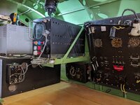
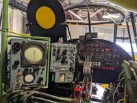
Here's a bonus picture of the actual work i've done so far in situ;
1648468304923.png


Cheers,
Rich
 
What I don't understand is there only being 4 digits displayed, I was wondering if it were the minutes/seconds of a longitude latitude reading.. but I see there's 84.04 South in this picture
But it is degrees and minutes as indicated by ° and '. Some more information in this book:
 
Secondly it's the Ground Position Indicator, I understand this unit would have projected a compass arrow onto a chart on the navigators table. It has two dials on it - they have 60 numbers for each direction, could it be in the theatre of Europe/Normandy they would have only used the EW dial between 10W and 10E ?
View attachment 662900
Possibly the navigator sets the north/south and east/west wind components on the knobs. For example, if wind is 25 knots from 30 degrees, it's equivalent to 22 knots from the north plus 12 knots from the east. Therefore, turn the left knob clockwise (toward the side marked N) to 22, and the left knob counterclockwise to 12. The old analog ASB-9A system formerly in the B-52H similarly divided wind into N/S and E/W components, though the display was on counters like a mechanical odometer. Also, wind determination was normally automatic via the doppler radar, though manual input was available as a backup.

The picture shows so little of the Ground Position Indicator system, I'm just guessing.
 
But it is degrees and minutes as indicated by ° and '. Some more information in this book:
thanks! Could just degrees and minutes be an acceptable accuracy for roughing a position? I have read in places that this device was more of an indication of your position
 
Possibly the navigator sets the north/south and east/west wind components on the knobs. For example, if wind is 25 knots from 30 degrees, it's equivalent to 22 knots from the north plus 12 knots from the east. Therefore, turn the left knob clockwise (toward the side marked N) to 22, and the left knob counterclockwise to 12. The old analog ASB-9A system formerly in the B-52H similarly divided wind into N/S and E/W components, though the display was on counters like a mechanical odometer. Also, wind determination was normally automatic via the doppler radar, though manual input was available as a backup.

The picture shows so little of the Ground Position Indicator system, I'm just guessing.
Great - this makes a lot more sense, now I realise the API was governing the position of the arrow on the chart. I had wondered whether the two dials on the GPI were for positioning, but what you say makes more sense. Just checked the beaufort wind scale, looks like 64+ is the top measurement, so makes sense for the dials to max out at 60 (I guess you wouldn't want to be be flying in anything more than 60?)

Here is a picture of the whole unit;

There's two knobs round the right hand side to alter the course and the other drum titled "wind direction / knots speed". The course I can get my head around, but the other drum, do you think it was split in two - the left portion of the drum would alter depending on the two large dials being set, and the speed portion on the right could be set using the knob on the right hand side..

Thanks for your input! It's challenging trying to recreate hard-to-research equipment without any navigation knowledge!

Rich

1648543858186.png
 
Ah. just watched a youtube video and he's lablled the parts of the GPI, "wind scales" for the two dials and the two knobs on the right hand side being wind speed and direction.. the course I assume was given by the API unit.. think my questions have been answered - thanks for your helps!

1648552394998.png
 
We are restoring Lancaster FM212. Here is a photo of our nav station that may be of help. FM212 is a Canadian-built Mk X so there are some differences but feel free to contact me if you need more photos. Nice work, btw. I look forward to flying the Lanc in DCS! Just as an FYI, if you are going for authenticity, you are missing the vibration mount and locking nuts for the Gee display as well as most of the instruments in the navigator's panel. I see you have added the lockwire but it is incorrect. I can supply more detailed photos if you wish.
 

Attachments

  • PXL_20220212_183551906.jpg
    PXL_20220212_183551906.jpg
    1.3 MB · Views: 31
  • PXL_20211124_190650567.jpg
    PXL_20211124_190650567.jpg
    1.7 MB · Views: 34
Last edited:
A snippet from a history of air navigation. Trying to find more details.

"Complementing these valuable navigational fixing aids, new dead
reckoning instruments were devised. The Air Position Indicator
provided a back-up to the navigator's own air plot; and was reset
when he got a fix. A modified set was introduced later which could be
sited over the navigation table such that, when the plotting chart was
aligned correctly, a pinpoint of light moving over the chart indicated
the still-air position of the aircraft. A further development enabled the
wind velocity (calculated or forecast) to be entered, thus producing the
Ground Position Indicator."
 
Thanks for the research! Apprecaite your efforts, so far i've think i've got the details down - with further help from this forum i've understood a small amount of wind scales (thus giving me the answer to the two large dials on the GPI)
As far as I understand, the API takes readings from instruments to calculate the rough position of the aircraft, it gives that position to the GPI which projects the symbol onto the chart, the GPI is also used to further estimate the aircrafts position taking in to consideration the drift created by the wind?
I have all these modelled, I've even got the projected symbol (see screenshots below)

I spent a majority of last night wrestling with the animation of this plotter too, which can be used alongside the projected symbol, seen in the centre of this screenshot.

I'm also modelling the dalton dead reckoning computer, which i'm assuming is going to help calculate the wind.. direction/scale?

The two other chaps working on this are dealing with the actual flight model/controls.. they've already put in a year or more of work

1648718055133.png


1648718180028.png
 

Users who are viewing this thread

Back