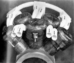
Radial Engine Design Layout

Ad: This forum contains affiliate links to products on Amazon and eBay. More information in Terms and rules

Sid327

Banned
349
183
Jan 28, 2010
TRNC
Considering the conventional way radials developed,

With the supercharger intakes at the rear of the engine and the exhaust manifolds, on some types at the front (which for these meant turning the exhaust gases through 180 degrees before routing them between the cylinders which affects exhaust flow and more importantly cooling airflow. ........Or the more conventional reverseflow head layout.

Did any engine company try mounting a supercharger on the front of a radial type engine, which would aid in ram air effect, give better crossflow head design and in the case of some particular engines (the radial sleeve valve type) allow a much shorter and less complicated exhaust layout.
Yes the prop reduction gear is in the way, but it forms a bell housing shape so an enlarged one could also house a centrifugal-type blower and all the gear driven accessories could be moved to the rear gearcase.

Any thoughts on it would be appreciated purely out of interest.

I understand some earlier radials that did use a cross-flow type head formed the exhaust manifolds at the front of the engine into circular collector to act as an anti-icing ring on the front of the engine cowling.

As an aside, and purely out of interest as it's off topic: I read an article where there was serious thought given to turning the clutch pressure plate (manual car) into a blower by adding centrifugal blower-type fins to the outer casing of the clutch assembly. Clearly an inner housing would be used to form a pressure chamber.
 
Such a design would only have disadvantages.

NACA testings had shown as soon as the early 1930s that radial engine front is where the airflow is most disrupted. So if you want to have "ram effect", you have to place your air intake elsewhere – say, wing roots, for example. I.e. after the engine….

It was also realized that the best design for a compressor inlet is a direct air intake, concentric with turbine axis, not a tangential one. It would be difficult to draw it, if in front of your air intake you find a propeller and its hub.

Also, the American practice of placing the mechanical compressor AFTER a turbo-compressor makes general arrangement drawing very difficult if supercharger is located in front of engine ! Especially if you must interpose an intercooler between turbo supercharger and mechanical supercharger !
And if you look at the very elaborate arrangements of an intake system like the P-47 one, you see immediately that the mechanical compressor is well in place behind the engine !

For the car clutch, it's a joke? A car clutch rotates at engine speed - 4,000 to 6,000 rpm -, a compressor runs at 30,000 rpm .... No match possible!
 
Hi Bretoal,

Many piston engined aircraft had intakes right behind the prop.
I wasn't thinking of turbochargers though, too much plumbing and pipework, let alone the complexity and weight penalty; just a centrifugal supercharger.
Most, if not all of the supercharger intakes are fed by ducting and turn through at least 90 degrees; 180 in others.
The advantage of being at the front is the cool air, as opposed to behind the engine in an enclosed space where all the heat generated from the engine builds up (it's enough to keep the pilot pretty warm behind the bulkhead, so assume it must be significant). Therefore you might not even need an aftercooler.
It is just an idea to invite people to think about it ......and probably shoot it down as too impractical.


Haha! No the car clutch thing wasn't a joke. It was apparently used by ''Smokey'' Yunick in a Nascar racer. I read about it in one of his books. IIRC it was this one:-
Amazon product ASIN 0931472067info about this flywheel supercharger here:-
How about a Smokey Yunick flywheel supercharger? (Page 1) — Bench Racing — The 24 Hours of Lemons Forums
OT Smokey Yunick's supercharger : Miatapower List Archive : MX-5 Miata World Forum : MX-5 Miata World

Bear in mind some supercharged production cars only use about 6-7psi (0.5 atm) of boost

Cheers, Steve.
 
Last edited:
Seriously interesting! (Unsure why there'd be induction losses).
Thank you and ''johnbr'' also.
:)

Have a look at this photo and consider the following
.
When the air enters the boxes what happens?
  • If the inside of the box is the same shape as the outside the air will become turbulent and Bernoulli's principle will be having a field day.
  • If it is round with vanes to assist the directional flow of the air into the pipes to the cylinders the airflow to the "second" cylinders and to cylinders downstream will be obstructed
  • When it leaves the box shape Bernoulli's principle will have another play
  • 1569129212641.png
 
Have a look at this photo and consider the following
.
When the air enters the boxes what happens?
  • If the inside of the box is the same shape as the outside the air will become turbulent and Bernoulli's principle will be having a field day.
  • If it is round with vanes to assist the directional flow of the air into the pipes to the cylinders the airflow to the "second" cylinders and to cylinders downstream will be obstructed
  • When it leaves the box shape Bernoulli's principle will have another play
  • View attachment 553548

Yes, Thanks.
I understand all that.
Not an easy task to project thoughts by keyboard, :)
I did not envisage a layout anything like this. It would be difficult to show without some means of creating an image which I don't have.

For a start it would need to be designed for a 7 or 9 cylinder engine to keep it simple and prove the effectiveness.
I imagined a supercharger fitted on the front of the crankcase and the hollow propshaft (suitably enlarged) used as the intake .....with the induction tubes from the s/c housing curved to each cylinder intake port in the same way they are on all radials except that they have fins for additional cooling. The prop drive which runs through the centre of the supercharger case has gears to drive the impeller at a suitable speed.
 
Its not a good idea to have stuff in the front of an aircooled aircraft engine. Ram air? So having say an under-slung air intake or on top all getting more airflow than they would closer to the engine centerline is not good?
 
Its not a good idea to have stuff in the front of an aircooled aircraft engine. Ram air? So having say an under-slung air intake or on top all getting more airflow than they would closer to the engine centerline is not good?


Yes, it's good :)

It worked for practically all radial engines made...
I was just trying to think outside the box and wondered if it could work.
 
try googling radial engine sueprchargers or cutaways to see what you are dealing with,

supercharger-radial-engine.jpg

This is for an R-2800 in a Hellcat. Now stick this on the front with the reduction gear in the middle or behind or?????
You have to get the air through a carb or throttle body at some point.

Hollow propshaft sounds good but how do you get the air out of the propshaft and into the impeller?

You do want the largest, least obstructed and smoothest air passages you can manage.

You also want to be able to reach and perform maintenance on some parts (or swap assemblies) with the least work. Like not have to pull propeller and propshaft to work on supercharger or pull supercharger apart to repair or replace the reduction gear.

800px-Cross_Section_of_a_Pratt_and_Whitney_R2800_Double_Wasp.jpg

On the R-2800 and most other large radials (Bristol excepted) the nose contained the reduction gear and the valve gear (cam ring/s) for the front row of cylinders. Impellers in the supercharger ran at around 7 to 10 times crankshaft speed and needed gears that would withstand 200-400hp (depending on engine), Yes you might be able to use a large diameter impeller turning at less rpm (but same tip speed) as the rear supercharger but you are still going to need a gear drive to run it. You are going to need a gear train for the cam ring/s.

You don't need to mount the magnetos on the front of the engine like P & W did but you are going to have an awful lot of stuff on the front of the engine and you are certainly not making the cooling problem any easier.

Note the size of the supercharger on the rear of the engine. The impeller is much smaller than the air passages in the diffuser.
 
try googling radial engine sueprchargers or cutaways to see what you are dealing with,

View attachment 555917
This is for an R-2800 in a Hellcat. Now stick this on the front with the reduction gear in the middle or behind or?????
You have to get the air through a carb or throttle body at some point.

Hollow propshaft sounds good but how do you get the air out of the propshaft and into the impeller?

You do want the largest, least obstructed and smoothest air passages you can manage.

You also want to be able to reach and perform maintenance on some parts (or swap assemblies) with the least work. Like not have to pull propeller and propshaft to work on supercharger or pull supercharger apart to repair or replace the reduction gear.

View attachment 555918
On the R-2800 and most other large radials (Bristol excepted) the nose contained the reduction gear and the valve gear (cam ring/s) for the front row of cylinders. Impellers in the supercharger ran at around 7 to 10 times crankshaft speed and needed gears that would withstand 200-400hp (depending on engine), Yes you might be able to use a large diameter impeller turning at less rpm (but same tip speed) as the rear supercharger but you are still going to need a gear drive to run it. You are going to need a gear train for the cam ring/s.

You don't need to mount the magnetos on the front of the engine like P & W did but you are going to have an awful lot of stuff on the front of the engine and you are certainly not making the cooling problem any easier.

Note the size of the supercharger on the rear of the engine. The impeller is much smaller than the air passages in the diffuser.


The hollow propshaft could run through to the centre of the supercharger impeller.
With the outer part of the propshaft having teeth ground on it for the reduction drive....
Fuel injection would be needed for this and fitted to the rear gearcase.
I only imagined a single stage blower for simplicity and proof of concept.
Traditional thought on transverse car engines used to have the intake at the back and exhaust at the front until some cranky nutter decided to turn the head around and found a better way and more power.
That's not to say it would work on a radial engine, but the advantages are a simpler exhaust system with the generated heat behind the engine
Cooler air and simplified ram air at the front of the unit.
.....But more complication.
Okay it's a failure but an idea only and thought it was worth stirring up some thoughts.
 
When talking radial AC engines there is no improving on the basic layout or arrangement of parts. There are places that could stand improving but not what this topic is about.
 

Users who are viewing this thread

Back