There are several interesting steam turbines powered aircraft projects from 1930-1970s.
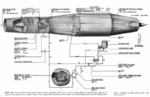
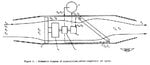
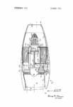
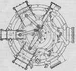
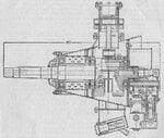
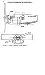
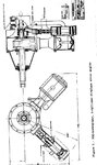
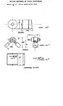
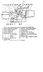
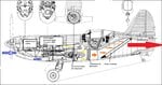
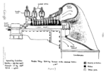
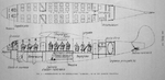
Campini and Rafaelli in Italy 1931 both proposed design of the ducted fan motorjet engine with IC engine replaced by steam turbine. Steam condenser was partially in wings and also inside ducted fan before jet nozzle:
Caproni-Campini C.C.2 – das zweite Strahlflugzeug der Welt | FliegerRevue X
https://ntrs.nasa.gov/archive/nasa/casi.ntrs.nasa.gov/19930094756.pdf
https://www.flightglobal.com/Flight...PDF#navpanes=0&scrollbar=0&page=1&view=FitH,0
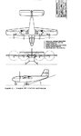
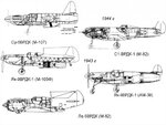
''News has now reached us that the Breguet Aircraft works at Toulouse is building an experimental jet-propelled machine to the designs of R.Leduc.This French engineer is well known for his work in connection with the problem of jet propulsion.As reported in the fourth article on the subject appearing in the October 9th, 1941, issue of Flight, Leduc patented a thermal jet system in the year 1933.' According to Inter Avia, the new experimental type is basically similar in principle to the Caproni-Campini machine, but with one important exception.Whereas the Italian craft uses a standard type of air-cooled radial engine to drive the air compressor unit, Leduc employs a steam turbine for this purpose.Of the VUIA type running at 3,000 r.p.m.under a steam pressure of 1,910 lb.per sq.in., the turbine is estimated to develop 1,200 h.p. Experiments, presumably on the test bed, are claimed to have given satisfactory results.No details are yet available, however, of either the boiler or the necessary condenser plant.Obviously, the steam system would have to operate on a closed cycle.Condensing raises further problems which are not easy of solution in an aircraft instal-lation.The condenser would, most likely be placed in the main air stream so that heat transferred from the steam would be usefully absorbed for the propulsive jet.The development of a jet-propelled aircraft employing such a system will be watched with intense interest by designers throughout the world.''
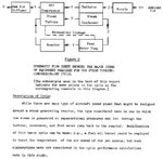
In 1944-1972 supercritical steam cycle was under consideration for aircrafts, hovercrafts and air cushion vehicles.
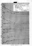
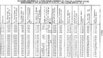
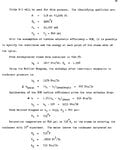
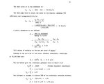
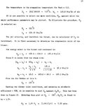
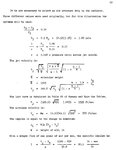
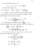
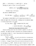
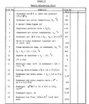
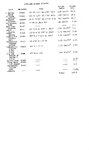
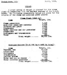
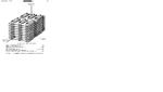
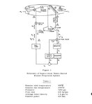
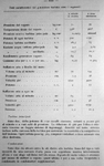
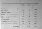
Calculated condenser performance for a steam turbine propeller power plant for aircraft ( 5000 hp steam turbines, 500 mph at 30,000 ft, total cycle efficiency 10-15%):
https://digital.library.unt.edu/ark:/67531/metadc58164/m2/1/high_res_d/19930085809.pdf
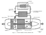
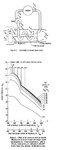
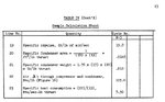
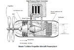
Supercritical-water Cycle for Aircraft Propulsion (design of steam turbine driven turbojet aircrafts flying at 30,000-50,000 ft at speed 0.9 Mach -600 mph with total efficiency 20-25%):
https://digital.library.unt.edu/ark:/67531/metadc52887/m2/1/high_res_d/19630003317.pdf
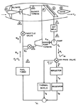
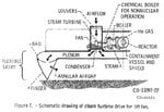
Parametric steam cycle analysis for nuclear powered bypass turbofan engine ( steam turbine driven turbofan engine designed for flight speed 0.8 Mach and altitude 35,000 ft, with cycle efficiency 20-30%):
http://hdl.handle.net/2060/19690030675
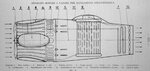
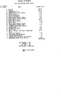
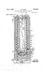
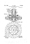
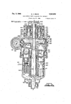
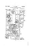
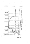
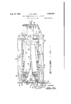
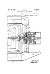
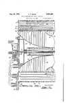
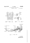
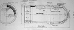
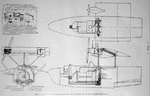
Pratt and Whitney in 1951-1953 designed large ducted blower jet engine aircraft with two 49100 hp main steam turbines and 7930 hp condensate pump steam turbine. Supercritical boiler absorbed 410 MW of thermal power. Maximum sea level speed was Mach 0.9!
Campini and Rafaelli in Italy 1931 both proposed design of the ducted fan motorjet engine with IC engine replaced by steam turbine. Steam condenser was partially in wings and also inside ducted fan before jet nozzle:
Caproni-Campini C.C.2 – das zweite Strahlflugzeug der Welt | FliegerRevue X
https://ntrs.nasa.gov/archive/nasa/casi.ntrs.nasa.gov/19930094756.pdf
https://www.flightglobal.com/Flight...PDF#navpanes=0&scrollbar=0&page=1&view=FitH,0
''News has now reached us that the Breguet Aircraft works at Toulouse is building an experimental jet-propelled machine to the designs of R.Leduc.This French engineer is well known for his work in connection with the problem of jet propulsion.As reported in the fourth article on the subject appearing in the October 9th, 1941, issue of Flight, Leduc patented a thermal jet system in the year 1933.' According to Inter Avia, the new experimental type is basically similar in principle to the Caproni-Campini machine, but with one important exception.Whereas the Italian craft uses a standard type of air-cooled radial engine to drive the air compressor unit, Leduc employs a steam turbine for this purpose.Of the VUIA type running at 3,000 r.p.m.under a steam pressure of 1,910 lb.per sq.in., the turbine is estimated to develop 1,200 h.p. Experiments, presumably on the test bed, are claimed to have given satisfactory results.No details are yet available, however, of either the boiler or the necessary condenser plant.Obviously, the steam system would have to operate on a closed cycle.Condensing raises further problems which are not easy of solution in an aircraft instal-lation.The condenser would, most likely be placed in the main air stream so that heat transferred from the steam would be usefully absorbed for the propulsive jet.The development of a jet-propelled aircraft employing such a system will be watched with intense interest by designers throughout the world.''
In 1944-1972 supercritical steam cycle was under consideration for aircrafts, hovercrafts and air cushion vehicles.
Calculated condenser performance for a steam turbine propeller power plant for aircraft ( 5000 hp steam turbines, 500 mph at 30,000 ft, total cycle efficiency 10-15%):
https://digital.library.unt.edu/ark:/67531/metadc58164/m2/1/high_res_d/19930085809.pdf
Supercritical-water Cycle for Aircraft Propulsion (design of steam turbine driven turbojet aircrafts flying at 30,000-50,000 ft at speed 0.9 Mach -600 mph with total efficiency 20-25%):
https://digital.library.unt.edu/ark:/67531/metadc52887/m2/1/high_res_d/19630003317.pdf
Parametric steam cycle analysis for nuclear powered bypass turbofan engine ( steam turbine driven turbofan engine designed for flight speed 0.8 Mach and altitude 35,000 ft, with cycle efficiency 20-30%):
http://hdl.handle.net/2060/19690030675
Pratt and Whitney in 1951-1953 designed large ducted blower jet engine aircraft with two 49100 hp main steam turbines and 7930 hp condensate pump steam turbine. Supercritical boiler absorbed 410 MW of thermal power. Maximum sea level speed was Mach 0.9!