Colin1
Senior Master Sergeant
I thought I'd lost this years ago
I've no idea if it's of any use to any of you but I'll post it up just the same; someone snail-mailed it to me as a word of caution before starting such a build. These old Revell kits are likely drying up now as a source and have been supplanted by better kits anyway. Just in case, though...
Revell's early 1/32 kits were not known for their accuracy and their Bf109G (or F) is the worst of the lot. This kit is so bad I almost did not include it in this section. However, since I did the drawings in 1/32 I decided to include it, concluding that there are plenty of intrepid souls out there who will attempt to correct this dog and perhaps do conversions to other variants.
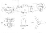
First, look at the side view drawing (32-1); the dashed line is the kit outline.
1. The spinner is not badly shaped, just a trifle too rounded at the front. The rear plate on the spinner is, however, too small in diameter and not thick enough; make a new one.
2. The rear section of this cowl section is a little high, sand this down. It is also a little too deep front to back; trim to fit.
3. As you can see by the dashed line, this cowl is too high and in a continuous curve. I think the plastic is thick enough to be sanded down. Don't forget to add the slightly raised piano hinge at the top of the cowl. The gun troughs also need correction. The rear is about in the right place but the trough is too long at the front; fill in and re-shape. While you're at it, re-cut the MG131 opening to fit the plan view. Don't forget to add the small circular blister (see plan view).
4. As you can see by the dashed line, this panel is too far back. You will have to add sheet to bring the edge forward (and correspondingly shorten the removable cowl piece) or if you do not plan to open the cowl, you can simply re-scribe the line after gluing everything.
4a. The MG131 breech bulges are not bad. The only problem (aside from a terrible fit) is the flange. There is a flange on the rear portion but the kit is far too thick; thin it down. The front part of the bulge has no flange, being an integral part of the cowl when its stamped out, so instead of removing the flange, fill it in between it and the bulge and blend into the cowl so no joint line is present.
5. Add the two scoops and the oil filler cover.
6. Note that the upper cowl, when removed, includes the upper exhaust shields and this piece of panel. The lower panel stays in place and extends up under the removable part. The kit's upper exhaust shields are far too thick and should be replaced by sheet plastic. The lower shields stiffeners are not on the kit and must be added.
7. I don't know how Revell wound up with this bulge but it must be changed. Since the plastic is too thin to withstand sanding, it is best to replace the whole undercowl, oil cooler included.
8. The oil cooler is mis-shapen at the front as the dashed line shows and the contours where it fits the cowl panel need to be redone.
9. As the dashed line shows the rear panel here is off; 7, 8 and 9 all concern the lower removable cowl and oil cooler. It will be difficult to correct although it can be done. I would recommend vac-forming over a corrected mold. You will have to add the oil cooler radiator itself inside the fairing and don't forget the brass drain tube in front, not a stiffener.
10. The forward wing root needs to be sanded back.
11. The cabin air scoop is wrong on the kit, remove and replace with a correct one depending on the variant. Remove the other one completely. Add the small crease/bulge in the upper cowl that allows the windshield washer to emerge.
12. The windscreen, main canopy and rear section are basically accurate in outline. The fanatic will want to re-work the complicated framing and vac-form the result since the kit canopy is a bit thick. The kit's pilot armour is supposed to be the early type but is not correct and must be corrected or replaced. For the glass type, it will have to be built from scratch.
13. The kit radio mast is pretty close for the early tall type but needs thinning to an airfoil shape. For the later versions, make the short mast. The base could also stand to be re-worked.
14. Add the DF loop and base as needed. Note that the loop always faces forward not sideways as often shown. The loop is pear-shaped, not a circle - see front view.
15. Don't forget the fuel filler cover and add the MW50 filler cover as needed. Add the primer fuel filler cover further back on the right side of the spine.
16. Re-scribe the fuselage access panel.
17. Note that the fuselage spine is too shallow, build up with putty.
18 and 18a. Those panel lines marked 18 are basically in the right place. Those marked 18a are in the wrong place and need to be removed, or added. The reason I didn't label the lines any further back has to do with 19 and 20.
19. The lower fuselage outline is far too shallow as you can see by the dashed line. Part of it has to be filled and part of it has to do with 20.
20. Now comes the real back-breaker of the kit. As you can see, the rear fuselage is about one panel section too short (causing in part, 17 and 19). The only way to correct this is to get another kit and add a section somewhere ahead of the vertical stabiliser. You must then putty, sand and file to eternity (it seems), correcting at the same time 17 and 19.
21. Now, if you lay the rudder/vertical stabiliser on the drawing (before or after you correct the fuselage) you will note that the lower part of the rudder is wrong (dashed line) and the rudder hinge line is wrong. Correct with sanding and sheet plastic strips.
22. The tail wheel is almost the right diameter, just a hair undersize for the early types G-1 and -2. The thickness is right for that type. The cast spokes are missing and would be a bitch to add. For other variants you'll have to add to the tail wheel both in diameter and thickness. The tail wheel yoke is just about right, actually not heavy enough - another bitch to correct.
23. The supercharger intake is wrong. Check it carefully in plan and side view.
32-2
As you can see by the dashed line, the drop tank is off just about everywhere. Fortunately, the plastic is thick enough to withstand sanding and rescribing. Note that 1 shows the bulge to be eliminated.
32-3
The dashed line shows how much correcting the stabiliser/elevator will need. No choice but to trim, fill and sand.
32-4
A single propeller blade is shown. As the dashed line shows, the kit blade is too long and too wide except at the bottom where it must be widened - ain't it fun? The extra width of the kit blade however, will come in handy on the wide blades of the AS and D-engined versions, so watch this carefully when doing the later versions.
32-5
Another back-breaker
1. If you line up the wing one way, the chord shows up too shallow all the way along the leading edge until you get to the tip (the leading edge slot also is off as shown by the dashed line). As you trace around the wingtip the rear shows up wrong as is the width of the aileron (dashed line).
1a. The trailing edge is too thick.
2. The wheel well bulge is far too large. The meeting of the bulge with the wing is a sharp line, not blended as in the kit.
32-6
1. This shows another way of looking at the wing chord problem; if you line up the tip part of the trailing edge, the leading edge shows up too wide (dashed line) instead of the reverse as depicted in 32-5.
2. The wheel well opening is very wrong (dashed line).
3. However, if you line up the wing as in #1, this part shows up wrong as well as the radiators. Any way you look at it, the wing chord will be another bitch.
This is not the end of the kit's problems. The interior is junk and should be started from scratch. The seat is salvageable with work. The main landing gear needs to be re-done (as well as the covers). The wheels are supposed to be the early cast spoked type and are close. The tyres are the right width and diameter for the early types. Remember, the later G tyres (G-3 on) are 3/8 inch wider in diameter on the rear.
The angle of the main gear is rotten - too far back. So you will have to trim out the mounting slots to allow the pegs to move the angle out more to match the drawings. I cannot emphasise too much for you to check and re-scribe every panel line, zu fastener etc as they are all wrong.
As for doing other variants with the tall tail, clear hood, refined cowl etc well, it's just straight work and building from scratch. The refined cowl is so different and so large that I suggest doing it in sections and vac-forming.
The tall tail will have to be built from thick sheet plastic like plastistruct.
There are a couple of vac-formed clear hoods available from specialty houses but I have not been impressed with them - make your own.
Don't forget all the antennas etc.
The corrections I have listed here cover the G-6.
I've no idea if it's of any use to any of you but I'll post it up just the same; someone snail-mailed it to me as a word of caution before starting such a build. These old Revell kits are likely drying up now as a source and have been supplanted by better kits anyway. Just in case, though...
Revell's early 1/32 kits were not known for their accuracy and their Bf109G (or F) is the worst of the lot. This kit is so bad I almost did not include it in this section. However, since I did the drawings in 1/32 I decided to include it, concluding that there are plenty of intrepid souls out there who will attempt to correct this dog and perhaps do conversions to other variants.
First, look at the side view drawing (32-1); the dashed line is the kit outline.
1. The spinner is not badly shaped, just a trifle too rounded at the front. The rear plate on the spinner is, however, too small in diameter and not thick enough; make a new one.
2. The rear section of this cowl section is a little high, sand this down. It is also a little too deep front to back; trim to fit.
3. As you can see by the dashed line, this cowl is too high and in a continuous curve. I think the plastic is thick enough to be sanded down. Don't forget to add the slightly raised piano hinge at the top of the cowl. The gun troughs also need correction. The rear is about in the right place but the trough is too long at the front; fill in and re-shape. While you're at it, re-cut the MG131 opening to fit the plan view. Don't forget to add the small circular blister (see plan view).
4. As you can see by the dashed line, this panel is too far back. You will have to add sheet to bring the edge forward (and correspondingly shorten the removable cowl piece) or if you do not plan to open the cowl, you can simply re-scribe the line after gluing everything.
4a. The MG131 breech bulges are not bad. The only problem (aside from a terrible fit) is the flange. There is a flange on the rear portion but the kit is far too thick; thin it down. The front part of the bulge has no flange, being an integral part of the cowl when its stamped out, so instead of removing the flange, fill it in between it and the bulge and blend into the cowl so no joint line is present.
5. Add the two scoops and the oil filler cover.
6. Note that the upper cowl, when removed, includes the upper exhaust shields and this piece of panel. The lower panel stays in place and extends up under the removable part. The kit's upper exhaust shields are far too thick and should be replaced by sheet plastic. The lower shields stiffeners are not on the kit and must be added.
7. I don't know how Revell wound up with this bulge but it must be changed. Since the plastic is too thin to withstand sanding, it is best to replace the whole undercowl, oil cooler included.
8. The oil cooler is mis-shapen at the front as the dashed line shows and the contours where it fits the cowl panel need to be redone.
9. As the dashed line shows the rear panel here is off; 7, 8 and 9 all concern the lower removable cowl and oil cooler. It will be difficult to correct although it can be done. I would recommend vac-forming over a corrected mold. You will have to add the oil cooler radiator itself inside the fairing and don't forget the brass drain tube in front, not a stiffener.
10. The forward wing root needs to be sanded back.
11. The cabin air scoop is wrong on the kit, remove and replace with a correct one depending on the variant. Remove the other one completely. Add the small crease/bulge in the upper cowl that allows the windshield washer to emerge.
12. The windscreen, main canopy and rear section are basically accurate in outline. The fanatic will want to re-work the complicated framing and vac-form the result since the kit canopy is a bit thick. The kit's pilot armour is supposed to be the early type but is not correct and must be corrected or replaced. For the glass type, it will have to be built from scratch.
13. The kit radio mast is pretty close for the early tall type but needs thinning to an airfoil shape. For the later versions, make the short mast. The base could also stand to be re-worked.
14. Add the DF loop and base as needed. Note that the loop always faces forward not sideways as often shown. The loop is pear-shaped, not a circle - see front view.
15. Don't forget the fuel filler cover and add the MW50 filler cover as needed. Add the primer fuel filler cover further back on the right side of the spine.
16. Re-scribe the fuselage access panel.
17. Note that the fuselage spine is too shallow, build up with putty.
18 and 18a. Those panel lines marked 18 are basically in the right place. Those marked 18a are in the wrong place and need to be removed, or added. The reason I didn't label the lines any further back has to do with 19 and 20.
19. The lower fuselage outline is far too shallow as you can see by the dashed line. Part of it has to be filled and part of it has to do with 20.
20. Now comes the real back-breaker of the kit. As you can see, the rear fuselage is about one panel section too short (causing in part, 17 and 19). The only way to correct this is to get another kit and add a section somewhere ahead of the vertical stabiliser. You must then putty, sand and file to eternity (it seems), correcting at the same time 17 and 19.
21. Now, if you lay the rudder/vertical stabiliser on the drawing (before or after you correct the fuselage) you will note that the lower part of the rudder is wrong (dashed line) and the rudder hinge line is wrong. Correct with sanding and sheet plastic strips.
22. The tail wheel is almost the right diameter, just a hair undersize for the early types G-1 and -2. The thickness is right for that type. The cast spokes are missing and would be a bitch to add. For other variants you'll have to add to the tail wheel both in diameter and thickness. The tail wheel yoke is just about right, actually not heavy enough - another bitch to correct.
23. The supercharger intake is wrong. Check it carefully in plan and side view.
32-2
As you can see by the dashed line, the drop tank is off just about everywhere. Fortunately, the plastic is thick enough to withstand sanding and rescribing. Note that 1 shows the bulge to be eliminated.
32-3
The dashed line shows how much correcting the stabiliser/elevator will need. No choice but to trim, fill and sand.
32-4
A single propeller blade is shown. As the dashed line shows, the kit blade is too long and too wide except at the bottom where it must be widened - ain't it fun? The extra width of the kit blade however, will come in handy on the wide blades of the AS and D-engined versions, so watch this carefully when doing the later versions.
32-5
Another back-breaker
1. If you line up the wing one way, the chord shows up too shallow all the way along the leading edge until you get to the tip (the leading edge slot also is off as shown by the dashed line). As you trace around the wingtip the rear shows up wrong as is the width of the aileron (dashed line).
1a. The trailing edge is too thick.
2. The wheel well bulge is far too large. The meeting of the bulge with the wing is a sharp line, not blended as in the kit.
32-6
1. This shows another way of looking at the wing chord problem; if you line up the tip part of the trailing edge, the leading edge shows up too wide (dashed line) instead of the reverse as depicted in 32-5.
2. The wheel well opening is very wrong (dashed line).
3. However, if you line up the wing as in #1, this part shows up wrong as well as the radiators. Any way you look at it, the wing chord will be another bitch.
This is not the end of the kit's problems. The interior is junk and should be started from scratch. The seat is salvageable with work. The main landing gear needs to be re-done (as well as the covers). The wheels are supposed to be the early cast spoked type and are close. The tyres are the right width and diameter for the early types. Remember, the later G tyres (G-3 on) are 3/8 inch wider in diameter on the rear.
The angle of the main gear is rotten - too far back. So you will have to trim out the mounting slots to allow the pegs to move the angle out more to match the drawings. I cannot emphasise too much for you to check and re-scribe every panel line, zu fastener etc as they are all wrong.
As for doing other variants with the tall tail, clear hood, refined cowl etc well, it's just straight work and building from scratch. The refined cowl is so different and so large that I suggest doing it in sections and vac-forming.
The tall tail will have to be built from thick sheet plastic like plastistruct.
There are a couple of vac-formed clear hoods available from specialty houses but I have not been impressed with them - make your own.
Don't forget all the antennas etc.
The corrections I have listed here cover the G-6.
 Honestly, I can't understand how they think folks will pay for a crap old kit when there are better one out there which are dearer but better value for money. From the looks of the 'remedial guide' posted above, this kit is strictly for the experts and the masochistic!