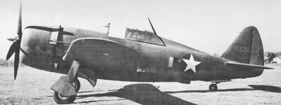
XP-47F

Ad: This forum contains affiliate links to products on Amazon and eBay. More information in Terms and rules

Lucio

Airman
26
15
Jul 29, 2019
Hi!
I´m trying to collect data to convert a 1/72 P-47D to P-47B to XP-47F.
A web search shows two drawings:
XP-47F.jpg


and:

XP-47F wing.png


As you can see, there are substantial differences between the two drawings regarding wing planform and skin panels. Do you know which one is correct?
Lower one came from a russian site and has a longer chord in the wing root. Flaps and ailerons are substantially bigger, also.
 
Are the differences in sizes between views within the same source, or between sources? Flaps and ailerons will frequently appear different in top view and bottom view, because they will often be "tucked under" the upper surface, for balance or other reasons. The flaps on P-47s were of a Fowler design, and would show quite a bit larger than the aileron, especially in bottom views, even in the experimental stages. I would therefore be more trusting of the first drawing, over the second. Panel lines are anyone's guess, without photo evidence. Since that was the laminar flow "X" bird, it may have been puttied and sanded smooth, with few or no visible panel lines, just the flaps and ailerons.
 
Last edited:
I see where the new wing only gave them a 1 mph increase in speed, but I would be interested to see what it did to the range. The laminar wing was one of the Mustangs' big advantages over planes such as the Spitfire which had the same engine but much shorter range. If the range was increased, the XP-47F would need to carry less fuel, thereby increasing the performance even more. Anyone have information on this?


-Irish
 
Are the differences in sizes between views within the same source, or between sources? Flaps and ailerons will frequently appear different in top view and bottom view, because they will often be "tucked under" the upper surface, for balance or other reasons. The flaps on P-47s were of a Fowler design, and would show quite a bit larger than the aileron, especially in bottom views, even in the experimental stages. I would therefore be more trusting of the first drawing, over the second. Panel lines are anyone's guess, without photo evidence. Since that was the laminar flow "X" bird, it may have been puttied and sanded smooth, with few or no visible panel lines, just the flaps and ailerons.
The differences are between sources.
The first drawing is signed by a certain B.F.C. Klein in 1975. The second one a got from a russian site and are not signed. There are significant differences between the two drawings.
 
Do consider the fact that prototype can change a lot as the designers find that "well, that didn't work. Well, back to the drawing board...." That being said, the access panels for the MG's make more sense in the lower view--remembering that we're talking Republic engineers, here....

And a 1 kt increase in top speed doesn't sound like a really good improvement in drag, so, I'd not expect the range to be noticeably better....

pgf
 
Here is a nice shot of the XP-47F I found on the Republic XP-47F Thunderbolt

The enlarged part of the wing trailing edge clearly shows that the flap and aileron were attached to the wing auxiliary iron. The straight line between the wing main body and flap+aileron section indicates the trapeze shape of the wing. What is more the flap had someting like a pipe attached to the trailing edge. And the aileron didn't reach the wing tip as it is drown in the first drowings by Klein above. Because of the flap and aileron top shape, it doesn't seem the bottom line for them is correct. For the reason I would say the accuracy of the drawings is questionable. IMHO the second diagram with the top+bottom wing surfaces seems to be more accurate.

XP-47F.jpg


XP-47F_.jpg
 
Here is a nice shot of the XP-47F I found on the Republic XP-47F Thunderbolt

The enlarged part of the wing trailing edge clearly shows that the flap and aileron were attached to the wing auxiliary iron. The straight line between the wing main body and flap+aileron section indicates the trapeze shape of the wing. What is more the flap had someting like a pipe attached to the trailing edge. And the aileron didn't reach the wing tip as it is drown in the first drowings by Klein above. Because of the flap and aileron top shape, it doesn't seem the bottom line for them is correct. For the reason I would say the accuracy of the drawings is questionable. IMHO the second diagram with the top+bottom wing surfaces seems to be more accurate.

Wurger,
I think you nailed it!
Thanks! I will discard Mr. Klein"s drawing and work with the russian one.
Cheers,
Lúcio
 
OK, now a new question: both drawings show "machine gub stubs" but i don´t think the XP-47Fs wing was armed or had provision for guns.
There´s a fuzzy picture that shows gun stubs ONLY IN THE LEFT WING but looks like if it was painted in the picture. A "doctored" picture. Why only the left wing would have provision for guns? Why stubs if the "normal" P-47 wing had just the holes for the barrels in the leading edge?
 
Believing the caption it's the XP-47F seen from the front quarter. Either the gun barrels (their stubs) or holes for tham can be noticed. IMHO these are the barrels with the shadows below each of these because of the sunny day the pic was taken on. Also it is very likely these weren't on the port wing only. The starboard one could have had them too . But there could have been holes only that could be pepered over. Attaching them is a logical corollary of the tests of the laminar air flow of the wing. However ,having them on one wing only could help to find the difference and influence on the airflow. The such protruded stubs could disrupt that in some way. So it should be taken into consideration during the tests as well.

repub-xp47f_.jpg
 
FWIW, even this is an older thread, I've been doing further research and came across this picture. The ailerons clearly end at the wing tip caps, so I would cast my vote in favor of the FIRST set of drawings, above. Also, no guns were carried on the "F" variant, but wooden dowels were used, instead, which can be seen in the earlier posted front view photo.

Ed
XP47F001c.jpeg
 
FWIW, even this is an older thread, I've been doing further research and came across this picture. The ailerons clearly end at the wing tip caps, so I would cast my vote in favor of the FIRST set of drawings, above. Also, no guns were carried on the "F" variant, but wooden dowels were used, instead, which can be seen in the earlier posted front view photo.

Ed
View attachment 703756
Shouldn't the second set of drawings be the right one then? Judging by the photos in Wurger's post #6, the ailerons seem to have a squared tip, and your picture shows that the wingtip aifoil's trailing edge is cut which would indicate that another part, namely the aileron, closes it.
 
Hi!
Regarding mr. B.F.C. Klein's drawing above, apart from the obvious inaccuracies in the wing, specially aileron shape, I would like to point to the fuselage lenght issue.
Two pictures in Warren M. Bodie's "Republic P-47 Thunderbolt From Seversky to Victory", page 219, shows clearly that the XP-47F had B-model standard fuselage lenght, no extra front section as in C and later models.
Cheers,
Lucio
20230209_011510.jpg
20230209_011415.jpg
 
Gotta agree with you Lucio. That picture is definitely of the unmodified "B". I found the same picture in Bodie's original article in Wings Magazine, Vol4No 3 June 1974, where he stated that he had so much P-47 material that he was going to have to write the book, because he had too many pictures to fit in his Wings P-47 series of articles.

I guess we'll have to wait and see what other info may come to light one day. Meanwhile, for modelers choosing to "hedge their bets", the original "B" nose conversion can easily be accomplished also, as I pointed out in my XP-47B Prototype build article HERE

Or, my more recent P-47B Double Twister article Here

I have been trying to correlate dates as to when the XP-47F flew with the wing, when it was modified with the longer nose, and the advent of the P-47B-1-RE, which was the first production appearance of the lengthened nose on a production P-47, but so far, not much luck finding a chart with data on what years/months each build block was built/delivered,
and when the mods occurred. Life would be much more simple had not the Republic records not been destroyed!

As for me, I'll hang tight and see what future information might bring, as the longer nose mod to the XP-47F is mentioned in several places...
 
Last edited:
The one thing that keeps me really curious about the fuselage length is that wherever I find an article, book, magazine or on-line, it invariably gives the length of the "F" model as around 36' 1" as opposed to the earlier P-47B lengths of around 35' 5", which is the 8" difference we're talking about. I say "around", because almost every site gives a different length dimension, varying from 35' 0" to 37'. I guess this could be lazy writers rounding up or down. Also, it is worth noting that there is very often a 3/4" difference shown here and there, which many feel is simply due to the length of the various types of propeller hubs used on the P-47's. Here, you have to roll your own!

Nevertheless, here is the entire photo from the magazine article mentioned above, which was the precursor to the book mention by Lucio, both from Brodie, the author. Also, for those interested, I am attaching a .pdf file of the original NACA Langley wind tunnel report on the laminar flow characteristics of the test of the "F" wing. One interesting thing about this report, is that it states that the original manufactured wing surface was so wavy that the boundary layer of air would not "stick" and they had to fill and sand the wing, much like on the P-51!

Ed
 

Attachments

  • P-47F005.jpg
    P-47F005.jpg
    63.6 KB · Views: 33
  • 19780078575.pdf
    3.6 MB · Views: 50

Users who are viewing this thread

Back