Wing Loadings: The Idiots Guide?

Ad: This forum contains affiliate links to products on Amazon and eBay. More information in Terms and rules

Bill,

That different airfoils reach Clmax at different AoA's is irrelevant cause in a max performance turn you're always riding close to the critical AoA and therefore Clmax.

And as for the L/D ratio, that is just yet another form of efficiency factor relating to how much lift you get for every amount of drag. The Cl is also an efficiency factor as it allows you to tell how much lift the wing produces pr. surface area.


Btw, I don't remember ever calling lift-loading an efficiency factor, could you point that out to me ? All I remember is calling it a simple way of accurately comparing a/c percentage wise.
 
Bill,

That different airfoils reach Clmax at different AoA's is irrelevant cause in a max performance turn you're always riding close to the critical AoA and therefore Clmax.

And, depending on the weight of the ship, the angle of the bank, and the velocity - one ship will stall out at Clmax and the other won't. The AoA will in probability be different betweeen the two -

And as for the L/D ratio, that is just yet another form of efficiency factor relating to how much lift you get for every amount of drag. The Cl is also an efficiency factor as it allows you to tell how much lift the wing produces pr. surface area.

L/D is THE factor describing an efficiency of a wing design. CL is NOT. CL is mathmatically = Lift/(q*A) where A is Wing area and q=dynamic pressure - for a specific AoA for that wing. Virtually every wing has the same Cl at an intermediate AoA - not equal to each other.

A truer expression of CL in context of comparisons with another is the rate of change of CL with increase with AoA.

The steeper the slope, the more efficient that wing because for smaller changes in AoA one gets same CL than an airfoil with a 'shallower' slope


Btw, I don't remember ever calling lift-loading an efficiency factor, could you point that out to me ? All I remember is calling it a simple way of accurately comparing a/c percentage wise.

Post 146 in P51D vs Spit XIV - I already went over that in my last post there this morning
 
The point is Bill that in a max performance turn both a/c are going to ride close to the critical AoA and therefore Clmax, so at what AoA each a/c stalls at is completely irrelevant.

As for wing AR, with an increase in wing AR you get an increase in L/D ratio i.e. a steeper Cl to AoA slope, plus the Clmax increases slightly. However with an increase in AR comes also a decrease in the critical AoA, which means the Clmax critical AoA are being reached sonner along the AoA range.
 
The point is Bill that in a max performance turn both a/c are going to ride close to the critical AoA and therefore Clmax, so at what AoA each a/c stalls at is completely irrelevant.

Sigh. Ok Soren - load your Ta 152H to max weight and fly against the P-51H at minimum weight and at SL - and repeat what you just said.

To simplify what I said above however, view it this way - stripping all variables away except Gross weight.

As the weight for the studied airframe increases, the lift loading in the turn increases over the lower weight. As the lift loading increases, the relative AoA for the same airspeed increases at the same velocity as the lower weight case. The AoA has to increase to get a high enough CL for that airspeed, weight and bank angle.. the higher loaded a/c (same exact airplane) attains max AoA and CLmax before the lighter airplane..

So explain again your thesis of dividing Lift Loading by CLmax?


As for wing AR, with an increase in wing AR you get an increase in L/D ratio i.e. a steeper Cl to AoA slope, plus the Clmax increases slightly. However with an increase in AR comes also a decrease in the critical AoA, which means the Clmax critical AoA are being reached sonner along the AoA range.

Yes, I know - I just said that two posts above on #60. You think I forgot?
 
The LE slats on a Bf109 are .462 of wingspan and .118 of mean chord. Thus, when the slats are extended, they increase the wing area (wetted area) by 9.1 sq ft.
Since adding wheel well covers on a 109 increased speed by 11 to 14 kmh and the bulges over the MG131 reduced speed by 8-9 kmh, it isn't hard to see the effect an increase of 9.1 sq ft wetted area would have on speed via skin friction. This is before considering form drag and interferance drag.

These effects would be most noticeable at higher speeds, ie combat maneuvering, and not so important at slower speeds, eg landing (following the drag formula where drag increases with the square of velocity).

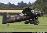
BTW, the Westland Lysander had automatic LE slats, as well as automatic trailing edge flaps. Here is a photo showing the slats in open position:
Photos: Westland Lysander IIIA Aircraft Pictures | Airliners.net
 

Attachments

  • Lysander, BernieC.jpg
    Lysander, BernieC.jpg
    54.9 KB · Views: 116
Guys

Isnt this meant to be an "Idiots Guide to Wing Loadings" meaning IMO that the explanations and opinions need to be simplified so that us less technical folks might have a chance of understanding what*the*hell you guys are talking about. It looks to me that this thread has lost the plot, in that it is damn near impossible to follow what you guys are on about

I did suggest that this be taken to the 'performance thread' some time ago.

It got off track on the wl/Clmax discussion which simply is nonsense aero.

Wing loading and lift loading are equivalent Numbers, at 1 g (where Weight = Lift in level flight), but Lift loading is a real concept in which all the aerodynamic loads on a wing in flight are implied - and expressed as Lift/Wing Area whereas the Wing Loading expressed as Wt/Area is a simple way to relate to the Gross Weight of the A/c.

As the a/c moves into high g turn in level flight, the weight remains the same
but the increasing bank angle forces a higher total lift to enable a lift vector in vertical direction to offset the weight...

Maybe simpler discussion is = at level flight/level wings the Lift Vector is 90 degrees to plane of wing and 100% vertical 'up' ('equal to weight) and directly opposite the weight vector pointing straight 'down'.

By the time the a/c has reached a bank angle of 45 degrees, the weight vector is still 100% straight down. The TOTAL lift vector is still normal (90 degrees to plane of wing) so that it must be increased enough so that the vector equal and oppsite the downward vertical vector of weight is offset perfectly (for level flight).

The Total lift vector is pointing 45 degrees from positive vertical axis (135 degrees from weight vector). The Total Lift Vector then is resolved to 1) an equal and opposite Vertical Lift component (cosine of Total Lift@45 degrees) and 2.) a Horizontal component inward (sine of Total Lift@45 degrees)

What you are solving for is to reduce the Total Lift (now pointing 45 degrees and normal to wing )into the vertical axis part that directly offsets weight, and the horizontal axis part that offsets intertia and continues to pull a/c into center of circle.

In level flight there is no 'horizontal' axis lift and the vertical axis component is same as Total Lift

The vertical lift component required to offset the weight is found by solving for the new AoA and CL at that velocity, which is required to give the wing enough lift at that velocity to achieve the Total Lift at that bank angle.

A diagram would replace all these words.

this is why the stick has to be pulled back increasingly (and rudder applied) to increase AoA to increase the lift at the same velocity.. and so on until speed is bled off, and AoA for CLmax reaches maximum and the bottom drops out.
 
The LE slats on a Bf109 are .462 of wingspan and .118 of mean chord. Thus, when the slats are extended, they increase the wing area (wetted area) by 9.1 sq ft.

The only increase in surface area would be that exposed by the opening of the slat. (the area of the surfaces of the resulting slot/gap in its self in between the slat and the wing; the trailing edge of the slat, and the "new" LE of the wing) the wing will increase by that .118 mean chord when the slat extends (as the slat's LE was acting as the wing LE).
 
The only increase in surface area would be that exposed by the opening of the slat. (the area of the surfaces of the resulting slot/gap in its self in between the slat and the wing; the trailing edge of the slat, and the "new" LE of the wing) the wing will increase by that .118 mean chord when the slat extends (as the slat's LE was acting as the wing LE).

correct KK - effectively any 'new' surface upon which flow acts and provides lift for the overall lifting surface... minus the gap between the slat and the LE of the wing.

The mean chord for the 'new wing' should be the length from the LE of the slat to the trailing edge of the wing. It should be ~ 1.118 more, which interestingly enough DECREASES the Aspect ratio of the wing by as much as 11%.

However, I don't recall seeing an analysis and subsequent study showing the test results showing the effect to adjusted AR for a slat depolyment.

interesting thought
 
Actually, I think I messed up my statement, that insight was accidental. :oops:

I meant to say that the wing area stays the same (if you include the slat's surface area), or the actual area of the wing its self decreases (the slat becomes separate).
But the area would not increase by the slat's surface area. The only increase would be the surface exposed by the opening of the slat. (the surface exposed between the slat's trailing edge and the wing's "new" leading edge)

So I'm not entirely sure how great of an effect this has on the wing's aspect ratio. The actual wing area (and chord) would be decreased by the slat extending as it takes a "chunk" out of the wing's LE. But then would the area of the extended slat be included in the wing area.
-From the standpoint of the wing behind the slat, the chord would be decreased, thickness/chord increased, and wing area decreased. By claidmore's figures chord would drop by 11%, thus thickness/chord increases by 12.36% and wing area would be reduced by roughly 11%. (this effect would be less if shorter chord slats were used of course)


Would the slat its self act as an airfoil generating lift independently of the "main" wing, or would it just be hanging there to create a channel to accelerate air over the wing and delaying boundary layer separation. (I would assume the latter given the decrease in L/D)
 
Actually, I think I messed up my statement, that insight was accidental. :oops:

I meant to say that the wing area stays the same (if you include the slat's surface area), or the actual area of the wing its self decreases (the slat becomes separate).
But the area would not increase by the slat's surface area. The only increase would be the surface exposed by the opening of the slat. (the surface exposed between the slat's trailing edge and the wing's "new" leading edge)

For retractable slats, there is usually an overlap of aft slat and 'under leading edge of the wing' - as the slat moves forward the top aft surface of the slat is 'new area' - as you say - so there is Some increase in area, although it should not be much one way or the other from 1/2 of the actual area of slot,

So I'm not entirely sure how great of an effect this has on the wing's aspect ratio. The actual wing area (and chord) would be decreased by the slat extending as it takes a "chunk" out of the wing's LE. But then would the area of the extended slat be included in the wing area.

I see it another way. I see the distance from trailing edge of the wing to leading edge of the airfoil 'extending' to a new airfoil of greater length and slightly thinner overall section - with a gap behind the slat and ahead of the new leading edge of the permanent wing (the part exposed by the extension of the slat).

So the 'new wing' has the same span but a local (increased) section with a longer chord!


-From the standpoint of the wing behind the slat, the chord would be decreased, thickness/chord increased, and wing area decreased. By claidmore's figures chord would drop by 11%, thus thickness/chord increases by 12.36% and wing area would be reduced by roughly 11%. (this effect would be less if shorter chord slats were used of course)

This is where we disagree -see above.

Would the slat its self act as an airfoil generating lift independently of the "main" wing, or would it just be hanging there to create a channel to accelerate air over the wing and delaying boundary layer separation. (I would assume the latter given the decrease in L/D)

Both. The extension of a second leading edge creates a slot behind the first leading edge and acts as a boundary control device to enable high energy air to be intriduced from UNDER the leading edge of the slat, enter the slot smoothly and smooth out the boundary layer which was starting to separtate before the slat deployed... but for it to work the airflow over the LE of the slat top surface has to be smooth (laminar) also - so it contributes some small amont of the lift distribution at that high AoA
 
I see it another way. I see the distance from trailing edge of the wing to leading edge of the airfoil 'extending' to a new airfoil of greater length and slightly thinner overall section - with a gap behind the slat and ahead of the new leading edge of the permanent wing (the part exposed by the extension of the slat).

So the 'new wing' has the same span but a local (increased) section with a longer chord!


I understand that, and I wasn't trying to say my other interptrtation was the correct one, I wasn't sure wich of the two is rally correct. (if either is) And that in respect to the wing ist self with the slats deployed (changes in area aside) the airfoil is thicker than that with the slats retracted.


The total chord would be increased in this respect, but the actual area has not increased (much) due to the gap behind the slat. Given that the aspect ratio is dependant on wing area and span, changing the wing in such a way as the slats do seem to confuse this a bit.
 
And in terms of actual wing area there shouldn't be any increase when the slats deploy. (wing area being a 2 dimentional figure as I understand it; the actual surface area of the wing being somewhat greater than 2x the wing area)
 
KK, the extended slat is still attached to the wing, and it still forms the leading edge of the wing, so it is still part of the wing. But we are arguing semantics.
I agree with drgondog that the slat extending increases the chord and reduces the aspect ratio. My understanding is that a lower aspect ratio means more drag (which is why gliders have high AR wings).

Here is a model illustrating the increase in 'wetted' surface area by extending the slat.
Take a block of material (the wing) 4 inches square, total of 16 inches (length doesn't matter for this model). Slice off a 1 inch segment (the slat). Now the original block (the wing) is 4x3x4x3, or 14 inches, and the slice (the slat) is 4 x 1 x 4 x 1 inches, or 10 inches. 14 + 10 = 24 inches, an increase of 8 inches. The actual percentage of increase in the case of a real wing and slat would be less of course, but the model illustrates the physics of it.
 
But in the region the slat is deployed, air isn't flowing straight over the slat LE and then over the rest of the wing. It flows over slat seperately and air accelerated under the slat (through the "hole") then flows over the uper surface of the wing, delaying boundery layer separation and thus increasing CLmax and crtical AoA.

The reason lower AR wings have lower lift to drag ratios (and lower Lift Coeficients) is due to the tip vortices. The greater the span, the proportionally smaller the area experiencing the vortices. (hence why elliptical and tapered wings redult in improved L/D as well, as well as winglets -tip-tanks of some jets often having a similar effect)
However, at high speed level flight or dives this has little effect on performance. (in high speed maneuvers it would be somewhat more important, but still much less than in the low speed regime)


With fixed slots at lower AoA, what you're saying would make some sense, but the airflow at high AoA is a fit different as air flows through the slot and over the wing, not over the slot.


------------------------------------

Now, that said, I think I should make this comparison:

1) (I'm not entirely sure on this one as the different airfoils may make things a bit more complex than I really understand.)
Take two identical aircraft with identical weight and engine power, with wings of identical planform and span, one (A) with a high-lift aifoil and the other (B) with a low-lift/low-drag airfoil but with LE slats, both having the same CL max. (albeit at different AoA)
Shouldn't aircraft A feature a higher lift to drag ratio at/near Clmax, thus retaining more speed and having a better maximum turn rate? (though probably at a greater radius than a/c B)

2) (This one I'm pretty sure of as the airfoil peroperties are the same with the slats retracted)
Alternatively, identical aircraft with wings of same AR, planform, and airfoil, but aircraft (A)'s wing being significantly larger, while a/c (B) uses a smaller wing with LE slats with the same maximum lift producing capability.

Wouldn't aircraft A have a higher turn rate due to the lower L/D? (again at a larger radius)


_In both cases aircraft (A) would have greater (parasitic) drag than (B) in all cases where the slats are retracted. Thus (A) would have lower top speeds, cruising speeds, and (high-speed/low-AoA) turn rates when compared to (B).

However, the service ceilings of the (A) aircraft will probably be higher.
 
Wouldn't it be simpler and more accurate to make comparisons with only one variable?

With fixed slots at lower AoA, what you're saying would make some sense, but the airflow at high AoA is a fit different as air flows through the slot and over the wing, not over the slot.

Air flows over the slat (leading edge of wing) and through the slot. The two then mix and form the 'attached' boundary layer.

In your second scenario, wingspan will be different, so induced drag will be different, offsetting the differeces in parasitic drag. By having two variables (size and LE Slats), it is difficult to make a comparison. That being said, Wing A in 2nd scenario should have slower initial turn, but better sustained turn.
 
No, in both cases I changed only one vaiable. I actually think example 2 is simpler as the airfoil on both a/c is the same.
In example 2) while the wing span is different, the wing planform and AR will be the same as I mentioned. The wing withoult slats is effectively a scaled-up version of the slatted wing, so maximum lift for both is the same. (the larger area making up for the higher CLmax of the other)

In comparison 1) I think there could be other issues as, while the wings are of identical size and planform, the use of different airfoils could result in different lift distribution.


And the airflow over the slat should flow over only the uper surface of the wing. (at high AoA, if fixed at low AoA, the air will flow a bit differently as the slat/slot leading edge is now acting as the wing LE while open)

slatlift.gif


virtualpilots.fi: 109myths
SLATTIENVAIKUTUS.jpg
 
No, in both cases I changed only one vaiable. I actually think example 2 is simpler as the airfoil on both a/c is the same.
In example 2) while the wing span is different, the wing planform and AR will be the same as I mentioned.

KK -theoretically the span remains the same, the airfoil where no slat exists (i.e inboard section of 109) is exactly the same as it was before slat deployed. When the slats deploy, the plan form changes at leading edge where the slats deploy. Aspect ratio should REDUCE as the slats deploy because for that region, the mean chor increases!


The wing withoult slats is effectively a scaled-up version of the slatted wing, so maximum lift for both is the same. (the larger area making up for the higher CLmax of the other)

No - I don't hink so. The slatted wing will give better high AoA control at low speeds, but the 'area' of a slatted wing is slighly hiher and the AR should be slightly lower. CLmax will be greater - CD should be greater - AR should be slightly lower - after deployment

And the airflow over the slat should flow over only the uper surface of the wing. (at high AoA, if fixed at low AoA, the air will flow a bit differently as the slat/slot leading edge is now acting as the wing LE while open)

No. the airflow is over the LE of the slat and the LE of the 'uncovered wing' - where they join to move over the wing surface aft of the slot.

slatlift.gif

Fowler flap operates with same principles
 
I meant the airflow from the slat goes over the LE of the wing and over the upper surface and does not flow allong the bottom surface of the wing. (at High AoA, as seen in the diagrams)


Not to start this whole argument up again, but the article virtualpilots.fi: 109myths which has the second diagram seems refer to "liftloading" (note, no space) in the context Soren was using it. I then did another google search of "liftloading" and found several other refrences to the term (all as one word) that seem to match Soren's usage. (the majority of which seem to be referring to the BF 109)

liftloading - Google Search

Why Carson was an idiot
This one in particular uses it in Soren's exact context. (additionally the Clmax figures seem much lower than what I've seen for the listed a/c)

However, one think I didn't know that that article mentions is that wing fences were tested on the Bf 109 and found to have similar benefits to the slats (albeit not as effective). And the fences were used operationally on the Hispano built 109's. (which lacked slats)
 

Users who are viewing this thread

Back