The H IX started as a private venture and the Hortens were very anxious to avoid failure so they avoided aerodynamic experiments wherever possible. A lower sweepback was used than on the H V and H VII and laminar flow wing sections were avoided as a potential source of trouble. Wing section at the junction with the center sections was 14% thick with maximum thickness at 30% and 1.8% zero Cmo camber line. At the centerline thickness was increased locally to 16% to house the crew. The tip section was symmetrical and 8% thick. Horten also believed that since the compressibility cosine correction to drag was based on the sweepback of the maximum thickness line, the ordinary section would show little disadvantage.
Wing twist was fixed by consideration of the critical Mach number of the underside of the tip section at top speed. This gave a maximum washout of 1.8°. Having fixed this, the CG was located to give trim at CL = 0.3 with elevons neutral. In deciding twist for high speed aircraft, CD values were considered in relation to local CL at operational top speed and altitude (10 km in the case of the H IX). Twist was arranged to give minimum overall drag consistent with trim requirements. The wing planform was designed to give a stall commencing at 0.3 to 0.4 of the semi-span.
Structure
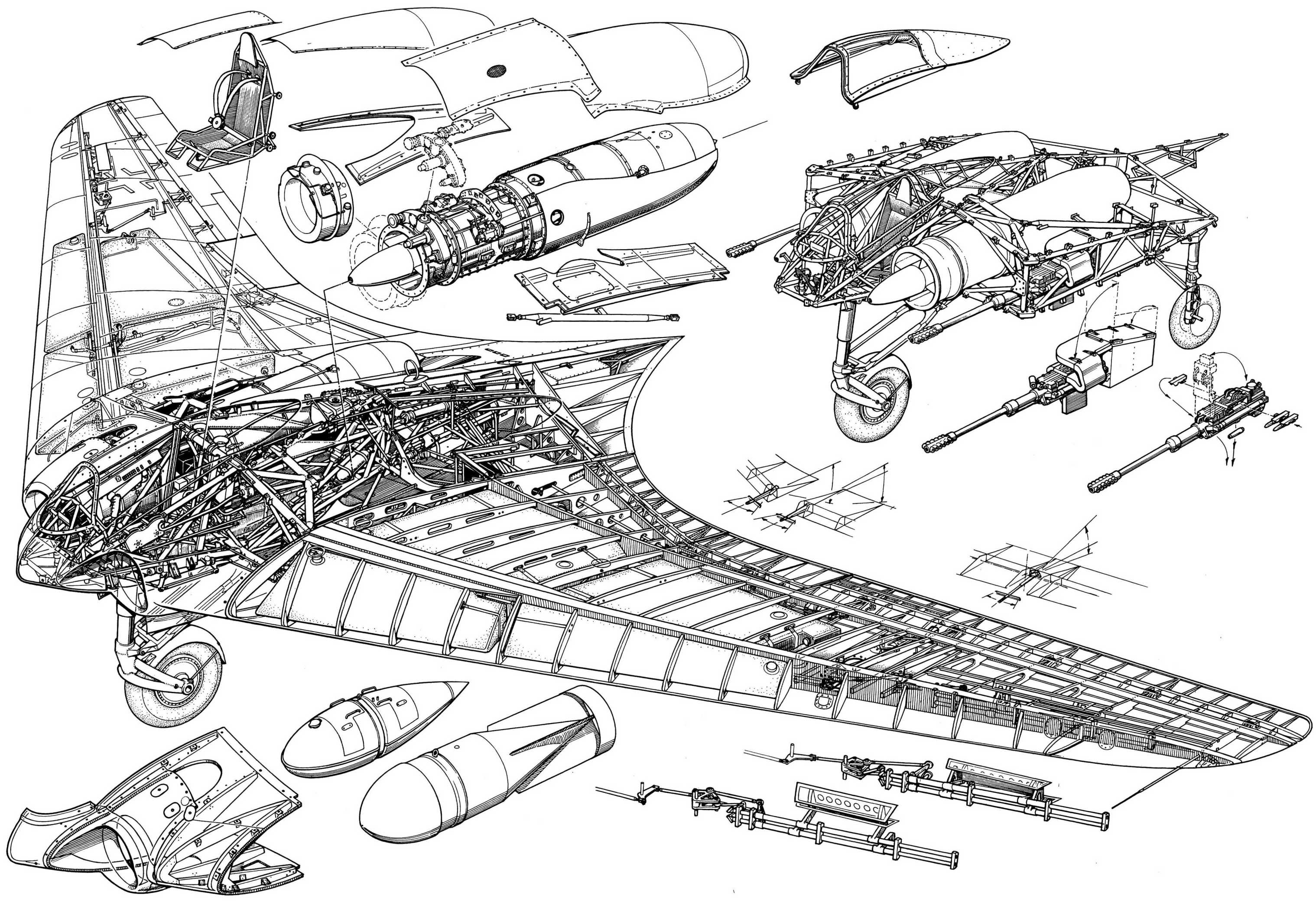
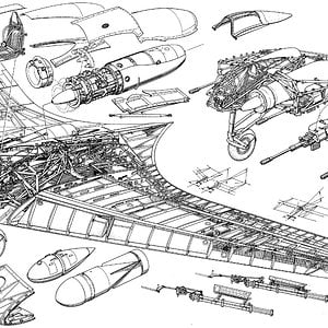
Wing structure comprised a main spar and one auxiliary spar or wooden construction with ply covering. The center section was built up from welded steel tube. Wing tips were all metal. The undercarriage was completely retractable and of tricycle type the front wheel folding backwards and the main wheels inwards. The nose wheel was castering and centered with a roller cam. When resting on the ground, wing incidence was 7° and the nose wheel took about 40% of the total weight.
Engine Installation
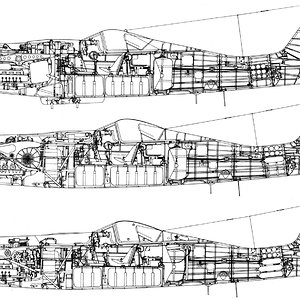
The jet engines were installed at -2° to the root chord and exhausted on the upper surface of the wing at 70% back from the nose (Fig. 22a & 22b). To protect the wings the surface was covered with metal plates aft of the jet pipe and cold air bled from the lower surface of the wing by a forward facing duct and introduced between the jet and the wing surface. The installation angle was such that in high speed flight the jest were parallel to the direction of flight.
Control System
Lateral and longitudinal control was by single stage elevon control flap with 25% Frise nose and compensating geared tap balance. (This system was also used on the H VII, see para. 4.6.) The pilots control column was fitted with a variable hinge point gadget, and by shifting the whole stick up about 2” the mechanical advantage could be doubled on the elevons for high-speed flight.
Directional control was by drag rudders. These were in two sections, slight movements of the rudder bar opening the small (outboard) section and giving sufficient control for high speed. At low speeds when courser control was necessary the large movement also opened the second spoiler, which started moving when the small one was fully open. By pressing both feet at once, both sets of spoilers could be operated simultaneously; this was stated to be a good method of steadying the aircraft on a target when aiming guns. The Hortens stated that the spoilers caused no buffeting and claimed an operating force of 1 kg for full rudder, with very little variation in speed. The operating mechanism is illustrated in Fig. 28. A change was made from the original H VII parallel link system to improve the control force characteristics. With the new system, aerodynamic forces could be closely balanced by correct venting of the spoiler web, leading the main control load to be supplied by a spring. The cover plate of the spoilers was spring loaded (Fig. 27) to form an effective seal with the rudders closed; this device was used on most Horten spoiler and dive brake designs.
On further models of the H IX it was proposed to fit the “trafficator” type rudder tried experimentally on the H VII.
Landing flaps consisted of plain trailing edge flaps (in four sections) on the wings, with a 3% chord lower surface spoiler running right across the center section, which functioned as a glide path control. The outer pair of plain flaps lowered 27° and the inner pair 30° – 35° on the glider version V.1. On V.2 mechanical trouble prevented the inner pair operating and all flying was done with the outer pair only. The center section spoiler could be used as a high speed brake and gave 1/3 g at 950 kph. No dive recovery flap was considered necessary.