A host of questions not deserving of their own individual posts.

Ad: This forum contains affiliate links to products on Amazon and eBay. More information in Terms and rules

How does multiplication work with psig, where the starting/sea level pressure is zero, and goes into negatives as we climb?
Starting Sea Level Pressure is not zero - it is, on a Standard Day, a column of 29.92 Inches of Mercury, or 2116.2 lbsf/square foot.
psig is a display for convenience, much like measuring temperature in Celsius of Fahrenheit, when it's really Kelvin and Rankine that count.
 
The comparison between impulse (velocity-driven) and reaction (pressure-driven) is well-presented in this image.
View attachment 880034
Those simplistic waterwheel images are not good representations of aircraft hot-gas turbines. The left illustration might possibly depict an impulse process, but the right illustration shows a mainly gravity process , not a reaction.
Far better understanding is available for those interested.
For those with a strong interest in WW2 aircraft Turbochargers and Superchargers, Calum Douglas has co-authored a fantastic book, "Turbo/Supercharger Compressors and Turbines for Aircraft Propulsion in WWII" (TSCT) and I strongly recommend it for a serious study. TSCT is a very detailed book, and so for those who just have an interest, some careful searching on the internet can provide some free information.

Eng
 
1: Why did turbochargers of WW2 seem not to make use of the velocity of the exhaust gas? The images and schematics I have seen universally depict the turbine as being a single-stage axial type, with the exhaust not being encouraged in any particular direction of rotation as it entered the housing. This suggests to me that it is only the pressure difference that is being capitalized upon, rather than the flow rate. This is in stark contrast to turbochargers of today, which (excluding some axial types used on generator engines) seem to be almost a mirror-image of their impellor counterparts. Was there some metallurgical obstacle to this at the time? Additionally, I would think that even if a purely axial turbine is being used, there would be benefit to a consistent direction of gas rotation - both to reduce turbulent losses and to extract more energy out of the exhaust.

2: What is the performance limit of a single-stage supercharger using a variable-speed drive? Essentially, what becomes the limiting factor of performance/efficiency/ceiling if the impellor can be made to rotate at any desired speed? The texts I have found that claim to depict this are never in a language that I speak, unfortunately.

3: What differentiates a two-speed supercharger from a two-stage supercharger in terms of performance/efficiency/ceiling? Is one system downright superior to the other given the same level of design?

Hi,
You should find the information to answer these questions in Calum Douglas' co-authored book, "Turbo/Supercharger Compressors and Turbines for Aircraft Propulsion in WWII" (TSCT). The book is not cheap, but it is worth every penny.

Eng
 
6: Was there ever any need for cooling air to be allowed into the engine compartment of a liquid-cooled engine, or was all cooling the job of the designated radiator? I would think the nuisance of water/glycol/oil cooling minute components that only barely need cooling at all to be a source of needless complexity.

There are many instances of local cooling arrangements for engine compartments. Generators often required a cool air feed and engine/compartment mounted guns usually needed airflow for cooling and purging gasses. During WW2, the Germans had serious problems with Sparkplugs and many aircraft needed local ducting of cooling air to cool the sparkplugs and the ignition harness.

Eng
 
I may be wrong, but I believe that the intent of that diagram is to present gravity as being the reaction force.
As opposed to the kinetic energy of the operating fluid (obviously there is still some momentum at play with the overshot waterwheel), it is the "desire" of the fluid to adhere to laws of physics that drives the turbine.
In the case of a reaction turbocharger, it is the pressure differential between the inside of the turbine housing and the external atmosphere. The exhaust gas "wants" to move from the former to the latter to equalize pressure, and is "willing" to do some work on the way to make it happen.
For the overshot waterwheel, the water "wants" to move downwards because of gravity, and is similarly "willing" to do some work on the way.

It is difficult, if not impossible, to construct a turbine that is purely of one type.
Water is not truly incompressible, so even an impulse (undershot) waterwheel will have an element of reaction to it. With an actual gas (rather than liquid) design it gets even more clearly impossible. To produce a purely impulse design there would need to be zero resistance presented by any part of the assembly, or a pressure drop would result.
A purely reaction turbine is barely possible, as I understand it. Continuing with the waterwheel metaphor, this would be an overshot wheel that ingests water along the axis of rotation, rather than perpendicular to it. Similarly, a gas turbine that somehow prevents any momentum from the operating fluid from acting on the turbine would be a pure reaction turbine.

I much agree with Shortround that it is hard to make a clear appraisal of a turbine as being of one type or the other - and not just because the extremes of the spectrum are seldom ideal!

I should get my hands on that book. I have much appreciated "The Secret Horsepower Race", I imagine this would be right up my alley as well.
 
You might be interested in Calums' book TSCT. It is primarily based on Prof Dr-Ing. Karl Kollmann's papers, all translated and expanded with explanation.
It is very important really, as Supercharging was a primary feature of all high output aero-engines.
Although the book is mostly based on German work, it does apply to all superchargers and contains many comparisons with Allied supercharging.
Despite the depth of theory and some Mathematics, the book is readable and understandable to a non-specialist, which I think is a great achievement. So, if
you are interested in the subject, you do not need to apply the maths to understand the concepts that are presented.

I attach a pic of the book cover and a page of the index, the book runs to 368 pages. Available from ASME Press, NY.

Cheers

Eng


tsct1_img_3426-jpg.jpg


tsct2_img_3427-jpg.jpg


Quote Reply
 
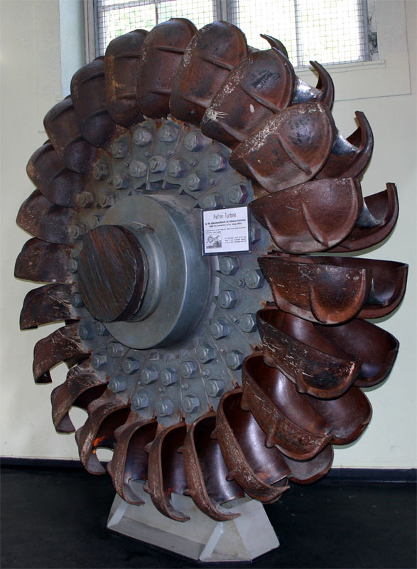
there are impulse water wheels and impulse steam turbines.
But they use kinetic energy and and not flow mass.

pelton-wheel-disused.jpg

With high pressure a small amount of water can do a lot of work. The high pressure/high speed water changes direction in the buckets and gives up a lot of it's energy.
The same principle can be used for steam turbines if a small but high speed turbine/engine is wanted. Many of these turbines used multiple nozzles spaced around the turbine wheel that allow for varying the actual flow while keeping the impact force high. Gating down a large nozzle to reduce flow kills the velocity of the stream hitting the bucket.

For steam while an impulse turbine has high efficiency for a single wheel/stage it does not take advantage of multiple stages. Multiple stages are more efficient, but they are heavier and bulkier.
Going back to the water wheel example, you can stick several water wheels in row in an undershot set up and get at least some work out of each of them before the water slows down/stagnates. hard to do with the overshot wheel but you are still depending on mass and gravity.
For the Pelton you can run a pipe from a point upstream of the wheel at a much higher elevation and use the elevation difference to generate more pressure at the wheel and use a tapered nozzle to accelerate the small quantity (relatively) of water to high speed to exert a lot of force on the wheel.
I never worked with a Pelton wheel but I worked with some fire trucks and fire nozzles. If you have a few hundred feet of elevation you can get water up to fire pump pressures and 80-100lbs of nozzle pressure can do a lot of work.

The over shot wheel maybe a sort of combination. Impact of the falling water helps turn the wheel but weight of the water in the buckets descending to the lower level does a lot of the work.
 
I do not quite understand your distinction between kinetic energy and flow mass. Mass is present in the equation for kinetic energy, of course.

It makes sense that impulse turbines are not ideal for multi-stage applications. I struggle to imagine a multi-stage impulse setup that would not be better executed with a single stage. (unless some extreme phenomenon like cavitation would be at play)

I contest the idea that multiple undershot water wheels would be better than a properly-designed single wheel. Obviously the speed of the water can never reach zero, or it would be unable to vacate the device to make room for the water to follow. That said, I think a single-stage undershot wheel could be produced to entirely de-energize the incoming water with a single stage. Imagine an undershot Pelton wheel with a "bucket speed" half the velocity of the incoming water, so the water is absolutely stationary as the bucket outpaces it. How could any more energy possibly be extracted from this system? The water is at a standstill, while also sitting at the lowest point in the device.
(In reality, there would have to be some sort of lower cavity for the water to fall into, lest it obstruct the incoming stream)

In fact, this is probably the best example of a pure impulse turbine there is - even better than a traditional undershot waterwheel.
 
I do not quite understand your distinction between kinetic energy and flow mass. Mass is present in the equation for kinetic energy, of course.
the effect of velocity in the equation is squared. Double the speed of the water stream give 4 times the energy. triple the speed of the water gives 9 times the energy.
Tripling the mass flow at the same speed gives 3 times the energy. Getting the energy out of the fast-moving stream is the problem.
I contest the idea that multiple undershot water wheels would be better than a properly-designed single wheel.
You may be right but moving water past the undershot wheel is wasted energy.

But classroom examples sometimes don't work in real life. Both piston steam engines and electric motors give max torque at stall, but if they are stalled they are performing no work at all. O% efficiency.
Output of the waterwheel/s need to be geared to actually perform work, like actually turn the grinding stones.
 
The fluid needing to keep some velocity/height so that it can vacate the working area is definitely the stumbling block of the "ideal" turbine here.
While I am aware that velocity plays a greater role than mass when it comes to kinetic energy, is the speed of the liquid really the limiting factor here?
I am sure that an ideal Pelton wheel could be produced to remove all kinetic energy from a stream of any characteristics.

On an unrelated note, I recently finished my third installment of questions.
 
From what I've read, the direct fuel injection is superior. It allows the increase of the valve overlap, and big overlap can up the power by 10% just by itself. Note that some engines moved from carburetor to fuel injection, while nobody reverted back to carburetor. The direct fuel injection also gives better mileage, again by some 10%.
Carb icing is not a thing on a fuel-injected engine. There is no need for choke and other things that mess with the air flow in the injected engine.
For a more professional take, see this video (never mind the catchy title): link

Wrt valve overlap, to a point. OTOH you're wasting some of the work that the supercharger is doing by blowing compressed intake air straight out into the exhaust.

As for carbs, yes. As Calum Douglas has pointed out in various formats, while a basic carburetor is very simple, a carburetor capable of operating at different altitudes, with wildly varying intake air temperatures, different mixture settings, orientations etc., is anything but. And that the British persisted with trying to use carburetors for high performance military aircraft for as long as they did was one of the greatest mistakes they did in engine development in the runup to the war and the early war years.

The turbo-compound engines were a thing post-war, even if the power recovered by the turbine was used by the engine directly.
There was also a thing of the turbo being the only means of supercharging, IOW the engine-stage supercharger was not there. That left a good deal of engine power to the engine itself, and was tested on the inter-war Lockheed P-30, it was mooted for the Ford's V-1650 engine (the S/C was with two stages on same shaft together with the turbine), and on the last R-4360s (4300 HP was hoped for, vs. 3500 on the engines with the engine-stage S/C).
It is used today on many engines in the cars, from Fiats to Porsches.

For turbo-compounding, I'm a fan of the Napier Nomad. But as one can see by reading about it, it was very complex and in the end pure turbine engines took over before it had the opportunity to establish itself.

And for turbos without mechanical supercharging, yes that's the norm these days. Mechanical superchargers are fairly rare nowadays, actually.
 
Wrt valve overlap, to a point. OTOH you're wasting some of the work that the supercharger is doing by blowing compressed intake air straight out into the exhaust.
But a Merlin is blowing some fuel/air mixture straight out of the exhaust. The Merlin still suffers from mixture loss during overlap, despite it's power reducing lower overlap cam timing and even then, it is compounded by the less complete exhaust scavenging that sub-optimal valve overlap suffers in attempts to improve SFC. Of course, for very high power settings (Boost), you may have to use ADI charge-cooling and accept some loss of the ADI component in a high valve overlap engine, but at all powers, the DFI high valve overlap engine can have a significant advantage in SFC.

Eng
 
But a Merlin is blowing some fuel/air mixture straight out of the exhaust. The Merlin still suffers from mixture loss during overlap, despite it's power reducing lower overlap cam timing and even then, it is compounded by the less complete exhaust scavenging that sub-optimal valve overlap suffers in attempts to improve SFC. Of course, for very high power settings (Boost), you may have to use ADI charge-cooling and accept some loss of the ADI component in a high valve overlap engine, but at all powers, the DFI high valve overlap engine can have a significant advantage in SFC.

Eng

I was maybe too imprecise, I was merely trying to say that there are also drawbacks in large valve overlap. As in so many things, the sweet spot is a compromise between several factors. And yes, it seems clear that having direct injection moves the sweet spot towards more overlap.
 
I was maybe too imprecise, I was merely trying to say that there are also drawbacks in large valve overlap. As in so many things, the sweet spot is a compromise between several factors. And yes, it seems clear that having direct injection moves the sweet spot towards more overlap.

The Merlin was indeed a great compromise in many ways. Calum Douglas has two main angles on his criticism of the Merlin carburation.
Firstly, the potential advantages of FI were missed by RR and misrepresented by some at the RAE.
Secondly, the consequent use of float carburettors and the resistance to the development of a British pressure carburettor led to the early Merlin being badly compromised in its performance under negative G.

Eng
 

5: What is the ideal radiator type, all things considered? The Meredith effect is a wonderful thing, but if it mandates that the radiator be a good distance away from the engine there is then a penalty of weight, complexity, and fragility that results from the need to plumb the plane. The leading-edge system of the mosquito, as well as the annular system favoured by Germany, both come to mind. Annoyingly, the rationales of the people who designed these planes are not as available as I would like. If anyone has such information, I would be most grateful.

From a rationale standpoint there are several questions in front of the aero engineer relative to an inline engine radiator placesment.
Foremost - What is the minimum size, particularly constrained by frontal area allowed (width constrained by width of fuselage, depth constrained by a variety of factors, but all point to drag headaches) which must pass sufficient volume of air through the heat transfer system.

Where might such a volume find a home in the airframe? If no such volume is available, the wings remain as only alternative. Ideally not too far from center of gravity.

Given a placement decided by required volume (or volumes of a 2-radiator choice like those imbedded in wing), how must the intake be designed to solve worst case engine cooling scenario? Climb, take-off, start/warm-up, taxi with no real airflow?

Must oil cooling co-exist due to lack of better alternatives?

I can't speak for anyone other than Ed Horkey, or anecdotally via written testimony by Atwood and Schmued, but all three agreed on ideal placement for the P-509 which morphed from P-509 to NA-73X to NA-73/83/91 with adjustable intake scoop and exit scoop, and then changed to fixed intake scoop with NA-97 with iteratively improvement through the XP-51B at Ames Field.

Both parasite drag and pressure drag considerations, combined with available volume behind the pilot deck, led to a placement behind the airflow boundary layer separation in the area of the fuselage/wing join and behind the attached turbulent flow separation region of the new NAA/NACA 45-100 airfoil/wing. Happily it also provided ample length Behind the radiator matrix to enable a contracting plenum with variable exit duct geometry to satisfy Meredith effect limited thrust achievement.


The Lightweight Mustangs improved the inlet plenum efficiency by re-locating the oil cooler to share in intercooler heat exchanger, then re-locating the header tank above the radiator. The resulting intake plenum design and even longer aft plenum achieved to lowest cooling drag for climb by 20% and net zero to positive thrust at high speed dash.
 
Both the Wright TC18 and GE turbines were axial impulse turbines. The TC18 used a "blow-down turbine" nozzlebox while the GE turbo used a "pressure turbine" nozzlebox. The advantage of the former is better efficiency at ~25,000ft and below. The disadvantages are you can't really control the darn thing with a simple butterfly wastegate and you need more complex exhaust piping and nozzlebox design. In terms of exhaust thrust, P&W expected a turbo-compound R-2800 to give ~100lbs (about 30% of a standard model) at take-off power. The XP-47J reportedly could do about the same at mil or combat power at altitude.
 
Drgondog, thanks for your commentary on the thought process of the designer.
Hopefully the radiator system would not be anything of an afterthought, but if designers of years past are at all like me I can see how the need to fit a cooling mechanism could be dismissed until the general aircraft layout has already been established - especially in an age of "slap evaporative cooling on it and call it a day".

In an attempt to avoid mounting anything under the wings or fuselage (to allow for ideal wing performance and centreline payload) I have thought of mounting mustang-style radiators on the flanks of the rear fuselage, exhausting on either side of the rudder. From the internal layouts of aircraft I have seen, there tends to be a good deal of free space back there - probably because it is far from the centre of gravity....
This radiator location could be justified by a need to restore the balance of the aircraft after a heavier engine is installed, but is probably not advisable as an initial decision.
After having this idea myself, I came across it online in the form of this hypothetical WW2 aircraft.

It is interesting to hear that idle and taxi conditions might be considered. Knowing the desperate drive for increased performance that was the second world war, it would not have surprised me to hear that some external solution was used to solve those problem areas (a leaf-blower into the radiator inlet during idle and taxi, perhaps!).

Was the Mustang radiator being behind the "turbulent point" of the wing of any significance?

Additionally, what would the penalties be for a radiator design which ingested the boundary layer separately rather than divert it around the intake, as the Mustang does? Think of the Bf 109 arrangement, but for a Mustang. I imagine this would consume more internal space, but probably improve the drag characteristics of the radiator by not demanding that the boundary layer be redirected so forcefully.

It is interesting to hear that the lightweight Mustangs modified the radiator arrangement within the duct. Any idea what drove the initial decision?

Thank you for your two cents!

 
Jugman, do you have diagrams of the two nozzleboxes, or the installations as a whole?
I am interested to see how the problem of control was solved (or mitigated).
 
In an attempt to avoid mounting anything under the wings or fuselage (to allow for ideal wing performance and centreline payload) I have thought of mounting mustang-style radiators on the flanks of the rear fuselage, exhausting on either side of the rudder. From the internal layouts of aircraft I have seen, there tends to be a good deal of free space back there - probably because it is far from the centre of gravity....

A couple of problems with this layout vs. a P-51 layout:

  • Where does the exhaust of the engine flow? Oh, right into the radiators! I can't imagine hot exhaust gasses nor soot accumulation on the radiator surfaces being particularly desirable.
  • Above the wing you have a zone of lower pressure, right where the radiator intakes are. In contrast, the P-51 radiator intake is below the wing where there is a high pressure zone.
This radiator location could be justified by a need to restore the balance of the aircraft after a heavier engine is installed, but is probably not advisable as an initial decision.
After having this idea myself, I came across it online in the form of this hypothetical WW2 aircraft.

Look at the length (and hence angle) of the ducting, and compare to the P-51? Too steep => flow separation and turbulence?

Was the Mustang radiator being behind the "turbulent point" of the wing of any significance?

No, since air doesn't normally flow from under the wing to the underside of the fuselage. But yes, after flowing past the fuselage for such an extended length, it's safe to assume the presence of a turbulent boundary layer. Hence the lip of the radiator inlet so that the inlet is in less disturbed air.

Additionally, what would the penalties be for a radiator design which ingested the boundary layer separately rather than divert it around the intake, as the Mustang does? Think of the Bf 109 arrangement, but for a Mustang. I imagine this would consume more internal space, but probably improve the drag characteristics of the radiator by not demanding that the boundary layer be redirected so forcefully.

Hard to say. Maybe someone interested and able could fire up a CFD simulation to give a definite answer; without that I suspect we're left to speculation. My guess would be that it wouldn't help, as the long extra ducting for directing the boundary layer would provide lots of surface area causing surface drag.
 

Users who are viewing this thread

Back