B-26 Dimensions & Diagrams (Outdated)

Ad: This forum contains affiliate links to products on Amazon and eBay. More information in Terms and rules

Maty12

Senior Airman
337
369
Nov 6, 2019
UPDATE: This thread has been discontinued and is full of incorrect information. For more current (and more accurate) information, see the thread B-26 Engineering Data/Technical Information (From Martin's Own Blueprints).

Hi all,

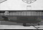
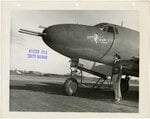
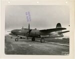
One of the multiple projects I've been trying to work on recently is building a 3d model of the early short wing B-26 Marauder (B-26, B-26A, B-26B-1 through B-26B-4, Marauder Mk. I), specifically the first production version, though modifying it to represent the other early versions wouldn't be too difficult after the model is finished. I've been doing research on the B-26 on and off since around 2016, and with my B-32 blueprints stuck in Daytona and 3 months with little to do before I can return, I figured I should get started on it. I've acquired quite a few manuals and diagrams, but my main obstacle seems to be the same as it was for the B-32: putting the pieces together. I have station diagrams and general arrangement drawings, but none list the size (height and width) of the fuselage's many frames and bulkheads, the few mentions often rounding up numbers, or just being very wrong. The documents also don't mention where the attachment points for the landing gear are, or at what height floors are mounted, that sort of stuff.

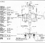
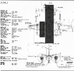
So I'm looking for any documents or diagrams that contain that missing information, that being the dimensions for the fuselage frames & bulkheads, landing gear assembly (and where the attachment points are), and any other parts I can come across. I'm also looking for one factory drawing in particular, but am not sure where to look. Thanks to Andrew Boehly at the Pima Air & Space Museum, I have a photo of an early inboard profile for the B-26, drawing number AP-B-26-075, but unfortunately only one sheet out of the 4 of the original drawing as the museum does not have the other ones. I'm trying to find the missing sheets.

I've contacted Stan Piet at the Glenn L. Martin Museum, and he has informed me that they do not have any manufacturer's diagrams for the Marauder. I plan on contacting the Smithsonian again when I am able, however since their replies are in the form of physical mail I wouldn't be able to receive anything until August.

Sorry if this post is a little rambly or oddly formatted, in general I'm creating this thread as a means to document my research into the Marauder and find additional information on it.

And speaking of documenting, I'm attaching the Excel file where I'm currently writing down what is located at what station on the plane and other information like that. I'm still filling it out, so quite a few entries are empty

Thanks for reading,
-Matt
 

Attachments

  • Stations.xlsx
    19.2 KB · Views: 339
Last edited:
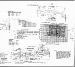
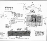
Been doing more research and had quite a few breakthroughs, most of them thanks to a couple of old blueprints I must have downloaded years ago, that I really wish I remembered the source of. They appear to be some sort of engineering drawing from the Glenn L. Martin Company itself, though the scan is very low resolution making quite a few numbers hard to read.
martin.b26.marauder.plans.diagrams-1.pngmartin.b26.marauder.plans.diagrams-2.png

I'm still updating the excel file, but my main finding has been that the wing's chord at the centerline of the ship (theoretical, as the real center section is straight) was designed as 168", tapering to 56" at the tip (again theoretical as the wingtip is rounded starting at station 364, 26" short of the end of the wing). This also answered a question I hadn't even thought about. Most blueprints from the aircraft's manuals list the wing's chord as 154.501" at station 46 (where the outer wing panel attaches to the straight center wing section), but using this number as well as other listed dimensions often led to misalignment. Using blender to replicate the simplified shape of the wing I found that the chord along that station is actually 154.78975(...)", which if projected horizontally (multiplied by the cos of the wing's incidence of 3.5 degrees) comes out to 154.5010359(...)", which was understandably rounded down to 154.501".

This has been quite helpful to me as it explained a few mathematical inconsistencies, and made some blueprints clearer, like the wing station diagram, which I originally took as being in the chord plane due to the listed dimensions.
Wing Station Diagram.PNG

Another thing I'm working on is figuring out what exactly did change when the wingspan was increased. Blueprints I have on the B-26B-15 variant still (mistakenly) list the wing chord at station 46 as 154.501" (Which is actually the horizontal projection of the chord, as previously established), but list the chord at the centerline as 166.437. I have yet to figure out if this is the actual chord or the horizontal projection, but it shouldn't be too difficult.

In general, I'm quite happy with these findings, as they prove that the blueprints don't have any miscalculated values or typos (so far), but rather are simply placed in incorrect planes of reference.
 
Matt,

That's quite an ambitious project and I hope that it leads to a flyable restoration!
I have an original B-26B-1 / B-26C Erection and Maintenance Manual (dated 25 Nov 1943 revised 10 Ju 1944) TO AN 01-35EB-2 and would be happy to look up some specific information. It doesn't appear to have the dimensions at each station though, just the station diagrams.

Good luck!

John
Thank you!

I'm not working on a restoration myself, but it would be very interesting if someone who was working on one found the information I'm trying to document useful, or could verify (or correct) this information for me. I might look into contacting someone working on a B-26 restoration, but don't know of any currently active.

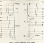
I don't have the Erection and Maintenance Manual for the B-26B-1/B-26C, and would love to take a look at it if you're willing to share. I'm also currently lacking the station diagram for the B-1/C's horizontal stabilizer, if that is included in that manual. It's included in a manual I do have, but the page itself wasn't scanned properly and looks like this:
Horizontal Stabilizer Station Diagram B-26C.PNG
It can be fixed (The fuselage station diagram was similarly improperly scanned, and I managed to patch it up well enough), but would take quite a few hours
 
It appears I've gotten confused and thought a lot of the pictures I have saved were of the MAPs B-26 during restoration, but they're actually from a restoration project being sold on platinumfighters, so there is an ongoing B-26 restoration, or at least there was when it was listed for sale back in 2018. I'm not sure who owns the aircraft currently. It appears to have bits of 40-1370, 40-1381 and 41- 31748. The latter is a B-26B, so I wonder how that will play out as at some point during B-26B production the nose gear strut mount was moved lower on the fuselage, resulting in the characteristic "bump" at the bottom of late B-26s' noses (the bump accommodates the new downlock), and on the aircraft's attitude while on the ground changing from tail-high to tail-low. This is sometimes incorrectly described as the landing gear strut having been lengthened/being longer. I do not know if this particular B-26B had the early landing gear or the latter one.

I'm also wondering what the real story is behind the B-26B production blocks. Wikipedia's list is rather short for the B variants:
  • B-26B—Single tail gun replaced with twin guns; belly-mounted "tunnel gun" added. (81 built)[41]
  • B-26B-1—Improved B-26B. (225 built)[41]
  • B-26B-2—Pratt & Whitney R-2800-41 radials. (96 built)[41]
  • B-26B-3—Larger carburetor intakes; upgrade to R-2800-43 radials. (28 built)[41]
  • B-26B-4—Improved B-26B-3. (211 built)[41]
  • B-26B-10 through B-26B-55 — Beginning with block 10, the wingspan was increased from 65 feet (20 m) to 71 feet (22 m) and flaps were added outboard of the engine nacelle to improve handling problems during landing caused by high wing loads. The vertical stabilizer height was increased from 19 feet 10 inches (6.05 m) to 21 feet 6 inches (6.55 m). Armament was increased from six to twelve .50 caliber machine guns; this was done in the forward section so that the B-26 could perform strafing missions. The tail gun was upgraded from manual to power operated. Armor was added to protect the pilot and copilot. (1,242 built)[42]
  • CB-26B—12 B-26Bs were converted into transport aircraft (all were delivered to the US Marine Corps for use in the Philippines).[43]
  • B-26C—Designation assigned to those B-26Bs built in Omaha, Nebraska instead of Baltimore, Maryland. Although nominally the B-26B-10 was the first variant to receive the longer wing, it was actually installed on B-26Cs before the B-26B-10, both being in production simultaneously. A total of 123 B-26Cs were used by the RAF and SAAF as the Marauder Mk II. Approximate cost then: $138,551.27/aircraft (1,210 built)
I'm particularly confused by the claim regarding the wing flaps, as the aircraft always had outboard and inboard flaps. Joe Baugher, on the other hand, goes into great detail into the specific production blocks, so much so that I can't copy all of it here, and will just link it instead:
Joe Baugher B-26
Joe Baugher B-26B
Joe Baugher B-26C

Basically, all indirect sources I can find claim that the B-26B-10-MA and B-26C-5-MO were the first long wing versions of the aircraft, but Martin's own manuals seem to refer to at least one long-wing model as the B-26B-1. Blueprints I've received from Andrew Boehly are similarly marked as B-26B-1, despite having the long wings, and the aircraft in the drawing's sideview has the serial number 41-31573 on it, which according to Joe Baugher belongs to the first B-26B-15 ever produced.

It's possible that Martin themselved refered to the short wing B-26Bs as the B-26B, and the long wing ones as B-26B-1. Manuals for the early marauders tend to list the variants as B-26, B-26A and B-26B (or exclude the B version all together), whereas late manuals (and blueprints) seem to equate the B-1 to the C. I find it hard to believe that any manual would ever include both short and long wing versions, since the designs are very different, especially in performance and flight characteristics.
 
The B-26B-1 was the official designation for the long wing B-26 development program. However, it was unofficially applied to the modification program for the B-26B MAs assigned to the 17th and 319th BGs.
The first long wing B-26s were B-26C-5s, produced in Omaha, beginning in August 1942. Baltimore followed with the B-26B-10 in January 1943. B-26Bs and Cs sharing the same block number were similar, but not identical. B-26C production ended in April 1944 with the -45 block. B-26B production continued to block -55 before production was switched to the "twisted wing" B-26F and B-26G.
Thanks for the info, Greg! That does explain quite a bit. I take it the short wing B-26B-MA was the designation for the short wing B-26Bs?
 
B-26B MA (Martin-Baltimore) was the initial designation for the B-26B run.
B-26B-1 was the long wing development program.
B-26B-2 was the next factory produced block, followed by the B-26B-3 and the B-26B-4. These were all short wing models.
Block -5 was the first long wing block, produced at the Omaha factory, and therefore designated B-26C-5 MO (Martin-Omaha)
B-26C-6 was a stripped down version envisioned for ground attack. These mostly served with the 323rd BG in the ETO, but were used in a conventional role, low level attack proving too hazardous over Europe.
 
B-26 MA #40-1370 and B-26 MA #40-1381 were hauled out of the boneyard at Naknek AK, (King Salmon) where they had both skidded off the runway on 16 Aug 1942. The remoteness of the crash sites of the Alaska based Marauders means there are more B-26 MA restoration birds than all other Marauders in existence today.
 
the original B-26B MAs had the 1850 bhp P&W R-2800-5s, with spinners and small air intakes. Additional plumbing was installed to permit mounting two 250 gallon bomb bay auxiliary tanks in the forward bay and two in the rear bay. Armament was a flexible .30 caliber Browning in the nose, with 600 rpg, deck turret with twin .50 caliber Brownings, 400 rpg, a .30 caliber tunnel gun with 600 rpg, and twin .50s in the tail with 1600 rpg. Additional sockets on the waist windows permitted the mounting of the tunnel gun on one of three positions. As was the case with the 22nd BG, extra .30 caliber guns were installed in these positions when the 69th and 70th Bomb Squadrons deployed. After Midway (the combat debut of the B-26B) the .30 caliber guns were upgraded to .50 caliber as soon as possible. Marauders assigned to the 69th BS were modified to mount a single fixed, forward firing .50 caliber Browning on the right side floor of the bombardier's compartment, fired by the pilot. The 70th BS installed additional sockets in the sides of the nosecone for up to two .30 caliber Brownings. The 70th also began receiving package guns in late 1942.
 
Thank you very much, Greg! This is all very useful information and will help me in modelling different variants of the aircraft after I finish the original B-26-MA.

I'm uploading the newest version of my Excel spreadsheet, and I've decided to put it on google drive so that I don't have to attach a new file every time I change something. It can be found here.

One of the more recent updates is that I've found the dihedral angle for the early Marauders. The blueprints listed it as 1d 45' (1.75d) along the chord plane and 1d 19' at the leading edge. I've basically built a jig around the measurements I did know and tried to make a wing that lined up. To my surprise, things line up almost perfectly if the angle along the chord plane is set to 1.828125d (1.75d + 1/16d + 1/64d), and that results in a leading edge angle of 1.322825, or roughly 1d 19'. I think it's safe to say that's the correct dihedral angle.
 
Both the Wing and Horizontal Stabilizer of the late B-26s show their heritage in an interesting way.

The wingtip of the long wing B-26s is unusually long, starting at station 364 (wing goes all the way to station 426), and the rear spar on this section is straight as opposed to the rest of the spar, which is angled forward. Station 364 is also where the wingtip for the short wing models start. The stations for both versions of the wing are identical for the most part, and I'm not entirely sure of what that means. The wings are also identical at the actual root (Station 46), but do not seem to be at the theoretical root or at the wingtips, suggesting the sweep angle and taper ratio are not the same between both wings.

The longer horizontal stabilizers similarly have a section from the station 20.75 (the actual root) to 45.25 where the forward spar is straight. It then angles backward all the way to the tip. Removing this section (which spans 24.5") from the span of the long stabilizers (168") reaches a total span of 143.5" for the short stabilizers, which is close to my previously found value of 143.75". I do not yet know if the long stabilizer is the old one + that 24.5" inboard section. The long elevators have a change in angle of their leading edge at the 44.688" spot and a much longer trim tab than older models, but this is not merely a case of adding an additional section, as the original trim tab seems to have been located closer to the inboard elevator hinge.

The vertical stabilizer is a bigger mystery, as there is no clear additional section on the station diagram, and the forward spar is not shown in it. In photos the stabilizer does seem to have a similar extension at the bottom to the one the horizontal stabilizer has, and the stabilizer is exactly 20" taller than the short models, but again the station diagram makes no note of this.
B-26 tail 3.png

I couldn't find better photos right now, but I'm sure there are plenty out there.

In general, I wonder what sections these aircraft have in common. Based on measurements, I think one could actually attach the outer wing of a late B-26 onto an early B-26. Of course, I don't know if the attachment points remained the same, or are strong enough to take the load. I don't think the same can be said for the stabilizers and their control surfaces. I'm quite interested in what the thought process was when lengthening these components. I'd imagine (and the station diagrams seem to support this) that a lot of it was based on keeping the maximum of parts possible unchanged, to minimize changes to the assembly line.
 
Update: using Blender, I've found that overlaying the two vertical stabilizers (including rudders) using the measurements I had lined up pretty well. I did require a correction to the sweep of the long stabilizer, originally listed as 32.33". After modifying this one number (to 33.07), the results speak for themselves. The two vertical stabilizers can be overlapped nearly perfectly, with differences of less than 1/64". I'd say that's good enough to conclude that the vertical stabilizer was lengthened by adding extensions spanning 20" to the bottom of the structure. The rudder trim tab has changed in size between the two versions, but its base is located at the same distance from Station 0 in both.
1590889052959.png

The two horizontal stabilizers, for their part, line up perfectly, with no corrections needed. The elevator trim tabs line up exactly, and it's clear that the tab was simply extended at the bottom.
1590890910716.png

And here's the complete "assembly":
1590891009397.png
 
So, I've had a theory for a while. The Marauder's fuselage seems to have almost no straight lines, and to me always looked a bit like an airfoil, so I decided to check how well a NACA 00xx-64 (All of the B-26's airfoils are -64) would line up with the fuselage using photoshop. Results are below. It would seem the fuselage is a NACA 0013-64 Airfoil (Approximated) with circular cross-section, modified by adding the cockpit section and a tail gunner's compartment. The engine nacelles seem to match a NACA 0019-64 (Again approximated) also with circular cross section, with the leading section cut off and modified to fit the carburetor, oil cooler and their respective air intakes, as well as the landing gear.
Side View.pngPhoto.pngTop View.png

I've also found that the long and short wings (pre-B-26F) have the same leading edge angle (8d 15' 57"). Excel sheet has been updated to contain this information.
 
Been a while since I've posted here, so figured I'd update y'all. First things first, I'm now in contact with Pat Rodgers, who owns 40-1370 and is also working on Pima's 41-131856, who has been helping me with pictures and some measurements.

Based on that, it would appear that the nose gear trunnion was originally placed on station 72 3/4", right under the cockpit floor, and that the later versions moved it 6" lower and 3 3/4" forwards, placing it at station 69" on these versions. The angle that the strut is mounted also changed from 11 degrees from the fuselage centerline to roughly 7.5 degrees, so that it could fit in the compartment without further modification.

The main landing gear is also mounted at 11 degrees, but the bottom portion of the strut is angled forwards by 9 degrees (to fit in the wheel well, I assume). The drag struts seem to be mounted at 45 degrees, but these angles are based on less accurate diagrams, so they could be incorrect. The service manual for the early B-26s lists this angle as 60 degrees, but the same manual also incorrectly lists the wing chord at the root as 154.501", so I'm taking that with a grain of salt.

These findings would explain why both main and nose landing gear legs seems to be mounted at the same angle in photos of early B-26s, but very different angles in photos of intermediate (B-26B-1/B-26C) aircraft. The difference seems to increase even further on the late (B-26F/G) aircraft, most likely due to the change in wing incidence, but I have not verified this yet.

Edit: Have since updated the excel spreadsheet with this information. It also contains some theories I have regarding the design of the nacelles and fuselage airfoils, that I currently do not have enough evidence to confirm or disprove. These mostly come from the fact that a lot of dimensions are very close to being multiples or divisors of 7 or 14.
 
Last edited:
Hey everyone, just a heads up. As I'm sure you've noticed, I've been doing a lot of research into the B-26, so I think it's pretty safe to say I'll be working on it for a while. I'm going to see if I can get some microfilm and other blueprints depending on what I can afford, and have been working out a system with some friends since I'm not currently in the US. The B-32 will stay on the backburner a while longer, purely because... it's a really complicated plane. Like, extremely complicated, inside and out, with plenty of auxiliary spars and rather odd design choices. I think it makes more sense to work on the B-26 for now, because I understand its structure and how its systems function a lot better, and it's just a much simpler design. Hopefully sometime relatively soon I'll have more to show y'all than just some weird airfoils ;)
 
Hey all, another update.

I'm in the process of purchasing microfilm blueprints for the B-26, but COVID has made doing so impossible for the time being. In the meantime, I have stumbled upon another conundrum: The mounting angle for the horizontal stabilizer.

B-26, B-26A, B-26B:

My most accurate set of blueprints (Drawing 5K-17988 or maybe SK-17988) lists no incidence value for the stabilizer, but shows the following:
horiz mounting angle 1.PNG

I do not know where the angle is being measured from or what it's measuring. It's also not clear if it's inches or degrees, or if there's a missing decimal point. The E&M manual states that the incidence is 0 degrees, presumably measured from the Thrust Line, as the wing incidence (3.5 degrees) is measured from the thrust line. The POH makes no reference to incidence angles.

B-26B-1, B-26C, B-26F, B-26G:
The blueprints for the B-26B-1 do not list an incidence value for the stabilizer, but again have values that might be a reference to it.
horiz mounting angle 2.PNG

I have no idea what the 1/2 and 1 1/2 values are in reference to, or what unit they are in. My guess would be that 1/2 is an angle (blueprint shows wing incidence as 3 1/2), but I have no theories regarding 1 1/2. The E&M manual for the B-1 & C models lists the stabilizer incidence as -0.5 degrees, again presumably in reference to the thrust line. Could this be what the 1/2 is referring to? It doesn't seem connected to the stabilizer's reference line/reference plane. The POH for these models lists the incidence as -5 degrees, which I assume is a typo from -0.5, but cannot verify. I don't have detailed blueprints for the F & G models or the E&M manual (not sure if it exists either), but the POH for said model makes no mention of incidence angles other that "wing incidence was increased by 3.5 degrees".
 
An update for August:
Still trying to sort out how purchasing microfilm will work, do have a fairly good idea of what rolls I need for now and will purchase others depending on necessity. My latest effort has been to try to make an accurate database of B-26 production, and of the different models. This is still WIP, but I have been using 3 different sources: The Martin Marauder B-26 by Victor C. Tannehill (as quoted in Joe Baugher's and the 320thbg's websites, I do not own the book), a database of serial numbers and a list of all Martin produced aircraft, courtesy of the Glenn L. Martin museum. They seem to agree on most numbers, but disagree on others.

All sources seem to agree that 5,266 B-26 aircraft were built by Martin, regardless of configuration.
-Tannehill describes the aircraft as originally produced, what the characteristics of the model were (sometimes incorrectly but most of the time accurately), and what they were converted into if conversions took place.
-The serial number database lists the aircraft's configurations as ordered/built. As such, it makes no mention of the B-26B-1, B-26C-6, XB-26D, XB-26E, AT-23A, TB-26G-15, TB-26G-25, JM-1 or JM-2.
-The Martin list reflects the final configuration of aircraft within the USAAC/USAAF, not what they were built as. It does not mention the JM-1 or JM-2.

In this post I will be using the shortened form "B-26(X)" to refer to all production blocks of that model, and will add the "-MA" suffix when talking about production blocks that have no numbers. In reality, all of these would have the "-MA" suffix or "-MO" (except the conversions, since they were not "produced") but I find that would make reading this tedious. In this text, "B-26A" represents both B-26A-MAs and B-26A-1s.

In most cases the number of aircraft converted from one configuration to another match up perfectly (Serial database + conversions according to Tannehill = Martin list), but there are notable discrepancies. Here is my breakdown of B-26 production according to those 3 sources:

All sources agree 201 B-26-MAs were built.

Tannehill and the Martin list both state that 109 of the 139 B-26As produced were B-26A-1-MAs, while the serial database claims 116 were. This discrepancy comes down to the last 7 B-26As produced, serials 41-7477 to 41-7483, which Tannehill & Martin claim were B-26As, while the database claims they were B-26A-1s. The only difference between the two types are the engines. This is the only time the serial number database contradicts the Martin list.

Tannehill claims that 307 B-26B-MA aircraft were built, of which 207 were converted into B-26B-1s and 100 remained as B-26B-MAs. The Martin list says there were 225 B-26B-1s and 81 B-26B-MAs, bringing the total to 306. The serial list claims 307 B-26B-MAs were built, but as previously stated does not provide any information about conversions.

Tannehill & the serial database state that there were 95 B-26B-2 aircraft were built, while the Martin list claims there were 96. To me, this suggests that one B-26B-MA was converted into a B-26B-2 as it would account for the missing B-26B-MA, but this is pure speculation.

All sources agree on the production of B-26B-3s to B-26B-35s, though Tannehill's descriptions range from accurate (various small things, but also explicit mention of the main wheels being enlarged from 47" diameter to 50", which was a theory I had) to an incorrect assessment (claiming the nose gear strut was lengthened by 6 inches instead of the trunnion being moved lower and forwards) to "I have no idea where he got this from" (claiming the B-26C-5 had landing gear doors with 3 sections, of which only one remained open when the gear was extended. Maybe he was reading into the B-25 at the time and confused the two? I do not know).

The Martin list states there were 101 B-26B-40 aircraft, 91 B-26B-45s and 208 AT-23As. The serial database lists 200 of each were built and no AT-23As, which would indicate 99 B-26B-40s and 109 B-26B-45s were converted into AT-23As. Tannehill agrees that 109 B-26B-45s were converted, but claims 141 B-26B-40s were converted into AT-23As, leading to a total of 250 AT-23As, 42 more than the Martin list. My excel spreadsheet describes only 139 when talking about Tannehill, as two of the 141 listed were later converted into XB-26Es.

The serial database states 175 B-26C-5 aircraft were built. The Martin list states there were 115 B-26C-5s and 60 B-26C-6s. The B-26C-6 was a conversion of the B-26C-5 that removed the co-pilot's position as well as some radio equipment. Naturally, the 60 B-26C-6s were converted from (and later converted back to) B-26C-5s. Tannehill confirms this, but claims only 59 were converted. I did not know what to make of this, but Joe Baugher's website has the answer (also quoted on the thread Martin B-26 Marauder):
The designation "XB-26E" was unofficially applied to a weight-reduced version of the B-26B/C that was produced by the Martin-Omaha Modification Center in January of 1943. B-26C-5-MO 41-34680 was selected for the tests.

Somewhat whimsically, the stripped-down aircraft was named Gypsy Rose, after the well-known stripper of the day, Gypsy Rose Lee. The gross weight was reduced by some 2600 pounds by deleting certain things such as provisions for AFCE, the SCR-287 liaison radio set, the navigator's seat, oxygen equipment, the toilet, astrocompass, astrodome, astro-graph, outlets for electrically-heated clothing, the K-38 camera mount, plus the rear bomb bay racks.

As part of the program, the dorsal turret was moved forward and mounted over the radio operator's compartment. This resulted in an improved field of fire, and the relocation actually improved the flight characteristics. The plane was tested at Wright Field in March of 1943. Maqny of the weight reductions tested ended up being applied to the "single-pilot" B-26C-5-MO.
My guess would be that Tannehill did not consider this aircraft a B-26C-6, since it's technically an XB-26E. We'll get into the ball of confusion that is the XB-26E in a bit, but first we'll finish up the B-26Cs

All sources agree on the production of B-26C-10 and B-26C-15 aircraft.

From B-26C-20 to B-26C-35 Tannehill and the Martin list/serial database agree on production, but disagree wildly about the number of aircraft converted to the AT-23B configuration:
B-26C-20s converted to AT-23Bs: 1 according to Tannehill, 0 according to Martin
B-26C-25s converted to AT-23Bs: 3 according to Tannehill, 1 according to Martin
B-26C-30s converted to AT-23Bs: 48 according to Tannehill, 23 according to Martin
B-26C-35s converted to AT-23Bs: 23 according to Tannehill, 200 according to Martin

All sources agree on production of B-26C-40s and on how many were converted into AT-23Bs.

The B-26C-45 is the weirdest one to me. The Martin list suggests that 25 of the 359 built were converted into AT-23Bs, and based on the total number of AT-23Bs listed, that a further 26 were built as AT-23Bs. The serial database supports the latter and cannot verify the former. Tannehill states that the last 26 B-26C-45s were built as AT-23Bs, which would mean all sources agree, BUT the serial numbers do not match up. The serial database lists the AT-23Bs as being aircraft 42-107471 to 42-107496, while Tannehill claims they were aircraft 42-95629 to 42-95737. Neither of these sets correspond to B-26C-45 serial numbers, so I'm not sure how to verify this.

The XB-26D was B-26-MA 40-1380, modified to test heated-surface deicing equipment.

The XB-26Es are very interesting and were hard to find information on. Joe Baugher was my only source on this for a while, but I believe I now have a full picture. The Martin list mentions 3 aircraft converted to this standard. Tannehill makes no claims about it and the serial number database has no reason to, as the XB-26Es were not conventionally ordered/produced.

For some reason, Martin used the "XB-26E" designation to refer to multiple aircraft. A post by joncarrfarrelly on whatifmodellers explains the situation best:
The XB-26E project involved modifications to four aircraft:
B-26C-5, 41-34680, Gypsy Rose dorsal turret moved forward to just behind the cockpit.

B-26B-40, 42-43319, twin .50MG and additional windows in the nose, four .50MG in the wings, engines with small scoops and extended nacelles, dorsal turret moved forward to position over the rear bomb bay, horn-balanced rudder.

B-26B-15, 41-31672, Pistol Packin' Mama, 37mm cannon and .50MG in nose, waist guns moved higher up the side of the fuselage, four .50MG in the wings, engines with small scoops and extended nacelles, horn-balanced rudder.

B-26B-40, 42-43459, wing incidence increased by 3.5 degrees, led to the F & G series.
41-34680 is listed as a B-26C-6 in the Martin list, explaining why it only mentions 3 XB-26Es instead of 4. It was indeed modified to B-26C-6 standard before being modified to this configuration, serving as the prototype for the B-26C-6 series. In his assessment of the XB-26E, Baugher mixes up 42-33190 and 41-31672, claiming they are one and the same, and that there is some other "bomber version" he does not know the serial number of. In reality, 42-43319 is that bomber version, and it does have a name: Wild Willie II. Here are some pictures of some of the XB-26Es:
XB-26E 41-34680 ''Gypsy Rose''.jpgXB-26E 41-31672 ''Pistol Packin' Mama!''.jpgXB-26E 41-31672 ''Pistol Packin' Mama!'' 2.jpgXB-26E 42-43319 ''Wild WIllie II''.jpg
I find the XB-26Es very interesting, and wonder how they would perform in combat. I do not have performance figures on them. The extended nacelles look quite good in my opinion and make the aircraft look like the North American XB-28. The horn-balanced rudder, easily visible in the pictures, is also a very interesting modification.

All sources agree on B-26F and B-26G production as well as how many of them were converted into TB-26s and AT-23s.

None of the sources mention the JM-1 or JM-2 as they were all AT-23Bs and TB-26Gs given to the USN with little modification. Joe Baugher's breakdown is accurate as far as I can tell.

I hope y'all have found this informative,
-Matt
 
Last edited:

Users who are viewing this thread

Back