High Aspect-Ratio vs. Low Aspect-Ratio

Ad: This forum contains affiliate links to products on Amazon and eBay. More information in Terms and rules

Apparently, NASA Langley did studies with a wind-tunnel model and found only changes were slight changes in longitudinal stability at high-"A", with the props spinning in the *same* direction. (not as if to counter the wing-tip vortices).
(reported by a commenter at the secretprojects forum)
I've requested a copy of that book from a local university to my local library

Amazon product ASIN 1580071163View: https://www.amazon.com/Radical-Wings-Wind-Tunnels-Advanced/dp/1580071163
 
As an Amazon Associate we earn from qualifying purchases.
John Frazer said:
Apparently, NASA Langley did studies with a wind-tunnel model and found only changes were slight changes in longitudinal stability at high-"A", with the props spinning in the *same* direction. (not as if to counter the wing-tip vortices).
Well, today's your lucky day: I know a person who's a member and they downloaded the file.

https://ntrs.nasa.gov/archive/nasa/casi.ntrs.nasa.gov/20050019375.pdf

I'd like to hear input from other people, particularly types such as drgondog, FLYBOYJ, KiwiBiggles, pbehn, Shortround6, swampyankee, wuzak, XBe02Drvr, and probably a few others I forgot for some reason regardless of their knowledge
 
We still need to see better data on the Arup planes. Only one wikipedia mention of glide ratio, with zero citations... And NACA was impressed with the efficiency of the S-2, and Hatfield spoke very highly of their efficiency as well. Models of them are very good at soaring, and the originals were lightly loaded.

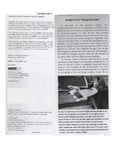
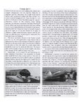
"Radical Wings and Wind Tunnels" is about Langley, and in the section of the V-173 it establishes that the planform was chosen to maximize wing-tip wash-around for the "parachute lift" it offers at low speed high A.
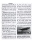
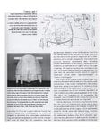
Tests with powered models in tunnels showed little effect from props spinning the other way -inward- at the tips, except more stability that way.
The enormous drag of the vortices is not present at cruise, and it's a mystery why they built the silly flappy props to counter what they'd specifically built to maximize, after establishing that it didn't help.

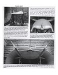
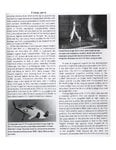
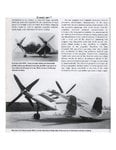
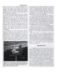
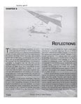
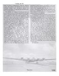
Photos added: scans from the book.
 

Attachments

  • Radical WIngs p-36.jpg
    Radical WIngs p-36.jpg
    111.3 KB · Views: 114
  • Radical WIngs p-37.jpeg
    Radical WIngs p-37.jpeg
    170.5 KB · Views: 168
  • Radical WIngs p-38.jpeg
    Radical WIngs p-38.jpeg
    184.8 KB · Views: 138
  • Radical WIngs p-39.jpeg
    Radical WIngs p-39.jpeg
    151.5 KB · Views: 199
  • Radical WIngs p-40.jpeg
    Radical WIngs p-40.jpeg
    127.8 KB · Views: 140
  • Radical WIngs p-41.jpeg
    Radical WIngs p-41.jpeg
    171.4 KB · Views: 149
  • Radical WIngs p-42.jpeg
    Radical WIngs p-42.jpeg
    117.7 KB · Views: 168
  • Radical WIngs p-43.jpeg
    Radical WIngs p-43.jpeg
    178.4 KB · Views: 132
  • Radical WIngs p-158.jpeg
    Radical WIngs p-158.jpeg
    123.2 KB · Views: 116
  • Radical WIngs p-159.jpeg
    Radical WIngs p-159.jpeg
    134.4 KB · Views: 112
John Frazer said:
We still need to see better data on the Arup planes.
I can actually agree to that. Short of building a model flight simulator... anybody here got some variation of X-plane?
Only one wikipedia mention of glide ratio, with zero citations...
Supposedly, the guy who led to the design of it was a podiatrist who somehow figured that a heel lift flew surprisingly well.
And NACA was impressed with the efficiency of the S-2, and Hatfield spoke very highly of their efficiency as well. Models of them are very good at soaring, and the originals were lightly loaded.
Yeah it basically seems that if the aspect ratio is high you can get more lift for less wing area, but if the wing area be sufficiently obscene, you can make it fly decently well.
"Radical Wings and Wind Tunnels" is about Langley, and in the section of the V-173 . . . Tests with powered models in tunnels showed little effect from props spinning the other way -inward- at the tips, except more stability that way.
Basically it seems to list two things

In the summary it says

The peak propulsive efficiency for β = 20-degrees and β = 30-degrees were increased 7 percent at CL ≅ 0.67 at 20 percent at CL ≅ 0.74, respectively, with the propellers rotating upward in the center than with the propellers rotating downward in the center. Indications are that the minimum forward-flight speed of the airplane for full-power operation at sea-level will be about 90 miles per hour.

Later on under effects of propeller operation on lift, it says

The effects of propeller operation on the left of the model are presented in figure 42 at angles of attack ranging from about 0-degrees to 30-degrees. At angles of attack of -0.5 degrees and -0.6 degrees for propeller blade angles of 20-degrees and 30-degrees, respectively, increases in coefficient of lift amounting to between 0.2 and 0.3 were measured for the propeller advance-diameter ratio ranges investigated. This change in lift coefficient is caused principally by the change in the local angles of attack of the wing induced by the slipstream rotation.

As the angle of attack is increased the change in lift-coefficient at a given propeller advance-diameter ratio increases. Calculations showed that about one-third to one-half the total increase in lift due to propeller operation at the high angles of attack results from the lift component of the propeller resultant force. Most of the remaining increase is attributed to the increased slipstream velocity over the wing.

Depending on how I read this the rotation of the propellers increased lift 7% when rotating upward from center, and reduced 20% when rotating downward from center, or at high AoA about 33.3% - 50% of the lift is produced by the rotation of the propellers and the rest from slipstream.

drgondog drgondog , I'm curious if this is correct...
it's a mystery why they built the silly flappy props
The vibration if I recall was caused at high AoA by span wise airflow. This effect is not dissimilar to advancing/retreating propellers..
 
Last edited:
The vibration if I recall was caused at high AoA by span wise airflow. This effect is not dissimilar to advancing/retreating propellers..

All sources say it was the power distribution system to allow either engine to take over and drive either prop, combined with the complexity of the flapping system. It seems US airplane & airplane engine makers were having bad luck designing prop extension shafts or distribution systems; maybe should have asked boat builders for help.

V-173 did nothing that the Arup hadn't demonstrated years before, without the consideration of the contra-props.
It's a mystery because the Arup had extreme STOL ability and high lift throughout the speed range, which was good. There was no apparent reason to innovate such extreme measures, for to counter the vortex which the aspect ratio was specifically designed to maximize at low speed, and which wasn't present to be a hindrance during normal flight.
Could they have thought the XF5U could actually be VERTOL so the V-173 was worth going ahead with? That extreme prospect was worth abandoning everything the Arup showed as entirely workable and practically revolutionary in capabilities?
 
All sources say it was the power distribution system to allow either engine to take over and drive either prop, combined with the complexity of the flapping system. It seems US airplane & airplane engine makers were having bad luck designing prop extension shafts or distribution systems; maybe should have asked boat builders for help.
Not just US designers, it's been a problem in aeronautics since the Wright brothers, linking a herky jerky reciprocating engine to a smoothly rotating propeller through a crank shaft extension, a driveshaft, or a gearbox light enough for aircraft use. The solutions that work in nautical applications are generally too heavy for aircraft use and are generally aimed at a lower RPM range. Aircraft structures tend to be more flexible than boat hulls and more likely to transmit rather than dampen vibration.
There was no apparent reason to innovate such extreme measures
How about asymmetric thrust? The loss of one engine without an interconnect would render a multi engine flapjack uncontrollable. The only thing that keeps a conventional multi engine plane straight with one out is the power of the rudder and the arm through which it is working. This power diminishes abruptly as speed decreases. A flapjack flying slowly at high AOA is not going to be able to handle an asymmetric thrust situation.
Cheers,
Wes
 
All sources say it was the power distribution system to allow either engine to take over and drive either prop, combined with the complexity of the flapping system.
The flapping system was designed to deal with the propellers being mounted on the tips
V-173 did nothing that the Arup hadn't demonstrated years before, without the consideration of the contra-props.
Counter-rotating propellers spin in opposing directions, contra-props are coaxial propellers (two rows of props which spin in opposition). While I'm uncertain the exact degree the rotation affected lift since I'm not 100% sure as to what I'm reading, but it seems to be fairly minimal at high-speed and more significant at low speed however significant/insignificant. Low speed would be where it would count so it's a nice touch.

In addition to the XF5U being built to take off in short distance, there was a desire to climb vertically and that depended on a lot of power: The ways to this would have hinged upon having a big propeller, without two engines it'd needed to be quite massive. Contra-rotation seem to reduce the required diameter, but I'm not sure how much. The fact is you'd have probably needed two anyway, though you could have put them mid-span with less difficulty. Depending on the effect of vortex cancellation (however small), it could have been worth it.
There was no apparent reason to innovate such extreme measures, for to counter the vortex which the aspect ratio was specifically designed to maximize at low speed
The Arup planes were designed for considerably lower speeds, and at least the S-2's wings were pretty thick in some areas. The V-173 was a demonstrator, so it had fixed-gears to verify the low speed of the equation (we could already build fast aircraft). The XF5U-1 was built for low and high speed, so a thinner wing would have been arguably more useful, and that could have affected the low-speed side of the equation.
Could they have thought the XF5U could actually be VERTOL
They had thought of making it able to lift off and rocket vertically, or be able to land vertically if I recall. I don't remember the source so you might not wish to quote me :p
 
How about asymmetric thrust? The loss of one engine without an interconnect would render a multi engine flapjack uncontrollable. The only thing that keeps a conventional multi engine plane straight with one out is the power of the rudder and the arm through which it is working. This power diminishes abruptly as speed decreases. A flapjack flying slowly at high AOA is not going to be able to handle an asymmetric thrust situation.

Only if it uses twin props so far off the cener axis line -'way out at the tips. Many normal twin-prop planes don't suffer too badly, most are fly-able with one engine out. There's no reason to suspect that a more normal twin arrangement on an extremely low aspect ratio plane would be any different.

And irrelevant with center-line props.
Boeing's 390 little test plane would have done everything the V-173 did, and probably been faster.
The Navy let Vought & Zimmerman explore the wing-tip down-ward turning props, after seeing that it made negligible difference, while ignoring the remarkable performance which the extremely low aspect ratio integral wing/body would have offered.
A half-deck on a converted merchant ship could have 2 spots, for planes like a Hellcat with more climb-rate, more speed, range and payload, and <35kt landing speed. Build it with jets like the Sikorsky thing, and nothing else they built for another 15+ years could have matched it, and nothing else could have been STOL capable.

Today, people say that extremely low aspect ratio needed the outward-turning props for (phantom) extreme drag during cruise, and since they didn't work, the planform couldnt work. Not true at all.
 
John Frazer said:
Only if it uses twin props so far off the cener axis line -'way out at the tips. Many normal twin-prop planes don't suffer too badly, most are fly-able with one engine out.
The V-173 and XF5U would not have crashed if one engine went out (if one propeller stopped spinning, that would be different): They were designed so that each engine can drive the other shaft. Should you lose an engine, the RPM of both props would slow down a lot, but you'd remain in control.

As for vortex cancellation on lift: Rotate the propellers the wrong way and lift drops by about 1/3 to 1/2 at high angles of attack which is where they would count most for lift. If you had no angular momentum to the propeller slip-stream, you would have an increase of 1/6 - 1/4 the amount of lift which is about 16.7% to 25%.
 
Only if it uses twin props so far off the cener axis line -'way out at the tips.
Isn't that exactly the configuration of the "flapjack"?
Many normal twin-prop planes don't suffer too badly, most are fly-able with one engine out. There's no reason to suspect that a more normal twin arrangement on an extremely low aspect ratio plane would be any different.
I've only got about 9,000 hours of twin prop time, so maybe I'm not qualified enough to comment, but here goes.
Yes "normal" twins fly quite well on one engine, AS LONG AS you keep the speed up. Get too slow, (like normal landing speed) and you don't have enough control authority to overcome the assymetric thrust. It's called VMC (Velocity Minimum Controllable), and in most twins, it's faster than normal touchdown speed. In most twins, single engine landings have to be accomplished with less flap and more speed, hence longer runways.
Now, what's the attraction of low aspect ratio aircraft like the flapjack?
Why, it's slow flight and STOL of course. Now put the props at the lateral limits of its discoid "wing", with the twin "micro" rudders aligned with the props, like the flapjack. Fail one prop at low airspeed, and how are you going to keep it straight? All features of your design point to a very high VMC. (Maximum assymetric thrust, minimum rudder effectiveness.)
Without a propeller drive "crosslink" (with all its friction losses), you're sunk. Also, to correct a mistaken idea perpetrated by Zipper, if you lost one engine in a "cross-linked" flapjack, you wouldn't lose prop RPM, (they're governed), but you would lose over half your thrust, and still have a controllable aircraft.
Cheers,
Wes
 
Isn't that exactly the configuration of the "flapjack"?
His idea was focusing on the fact that part of the massive lift benefit of the V-173 & XF5U came from the massive propeller slipstream itself. Even at low-speeds where AoA is the highest and vortex-strength the most extreme, with the propellers designed to reverse the wrong way, you'd have a loss lift ranging from 33-1/3 to 50%, which is obviously quite substantial, but with no angular momentum (which is a true test of the effect since rotating them the wrong way actually would intensify the vortex, and rotating them the right way will neutralize the vortex), you would see half that loss -- 16-2/3% to 25% produced by vortex cancellation. This would result in 75% to 89-1/3% produced by simply blowing massive quantities of air over the area of the wing.

His contention was if the propellers were mounted further inward, this would reduce the amount of yaw produced by loss of thrust, increase in drag, and roll produced both by yaw and loss of slipstream over the wing affected. Vortex cancellation would be less to nonexistent, but engine-out would be better in theory.

Functionally, since the design worked heavily on the propellers blowing nearly the full span, the propellers would have to be huge regardless and the engines would have to be placed further out than the actual XF5U mounted them to cover that much of the wing, and the propellers would still require long shafts to avoid choosing the cockpit off (unless it was recessed further back). I assume that the production of roll-rate would be quite high if an engine failed with the sudden change in lift, as low aspect-ratio wings usually have good roll-rates, and yaw would probably be quite noteworthy as well with the large thrust produced
Also, to correct a mistaken idea perpetrated by Zipper, if you lost one engine in a "cross-linked" flapjack, you wouldn't lose prop RPM, (they're governed), but you would lose over half your thrust, and still have a controllable aircraft.
Sorry about that
 
His contention was if the propellers were mounted further inward, this would reduce the amount of yaw produced by loss of thrust, increase in drag, and roll produced both by yaw and loss of slipstream over the wing affected.
You can't have it both ways. Move the props (rotors?) inward, and you limit their diameter and lose some of your full-span slipstream, for not much improvement in assymetric handling. Leave them out near the wingtips and you get better slipstream/span coverage at the cost of truly impossible single engine handling. Gotta have that propeller interconnect.
Cheers,
Wes
 
You can't have it both ways.
Plus with the existent diameter, you'd only be able to move it in a small ways, and even if you reduced the diameter a skosh, to cover the wing you'd still need a substantial diameter and would have to move the engine further outwards which would be difficult to do, would probably still have poor engine-out performance, and you'd probably need to increase the wingspan to make the cowl and airframe to blend right.
Move the props (rotors?) inward, and you limit their diameter and lose some of your full-span slipstream, for not much improvement in assymetric handling. Leave them out near the wingtips and you get better slipstream/span coverage at the cost of truly impossible single engine handling. Gotta have that propeller interconnect.
The other possibility that John Frazer proposed was the Boeing 390 (he listed it as the Boeing 396, I couldn't find it in searches, so I just entered "Boeing Flapjack" and got the right answer) which was similar to the Arup S-2 and S-4 arrangement.

The S-2 has a listed stall speed of 20 knots, but there's no loaded weight figure. Using the Arup S-4 as an estimate which is around 1200 pounds fully loaded with a 273 square foot area, I get a wing-loading of 4.395. Assuming the stall-speed was the same (which is an assumption), the XF5U weighs 16722 lbs with 475 square feet of wing area: Wing-loading is 35.2, which produces an 8-fold increase in wing-loading and a stall speed increase of 2.83 which would be 56 knots. I'd say that's not bad considering the earlier F4F-3 had a stall speed of around 64.7 knots either lightly loaded or empty. However the XF5U offered a stall speed ranging of around 20-40 knots which seems a bit better (and probably owing to better coverage of the wing by slipstream).

The Boeing 390 I have no figures for in terms of dimensions and weight, John Frazer John Frazer might have some figures here, but with an R-4360 powering it, the generally listed as 3400 hp WEP/3000 hp MIL/2500 hp Normal; the R-2000 rated at 1600/1350/1100 in respective order, with 2 of them you'd have 3200/2700/2200 which would show an advantage for the Boeing 390, and two engines do have higher installation drag so I guess you'd have a slight drag reduction on that.

The power loading is better for the Model 390 than the Arup S-4 which might indicate an improvement in slipstream based lift and with a contra-rotating propeller, there'd be no angular momentum to the flow which would probably result in a faster velocity over the wings. The coverage over the wing would be less so the question basically is which works better -- I have no answer.

That being said: I would say the biggest problem with the XF5U was that Vought didn't add the flapping propeller blades off the bat (something which Zimmerman wanted), and decided to add them later. Not sure how much time would have been spared, admittedly.
 
Last edited:
Not true that it gained the extra lift at very low speed from slip-stream from the outward-rotating props. It's stated that 3-4x lift for such a speed, comes from the planform.
It's the same phenomena for the Arup, the Nemeth, the Little Bird, the Facetmobile. (all of which were stall-proof, also due to the "vortex parachute" it creates behind/above it while flying very slow with high A)
Wainfan put it into verified science, just as Zimmerman established that the very low aspect-ratio gave it the extra lift at low speed.

He was after something else. The very-slow speed for the clean all-wing-body, was due solely to the planform and type, not the props.
 
Not true that it gained the extra lift at very low speed from slip-stream from the outward-rotating props.
From what the NACA report said, from what I remember, the biggest variable was the slipstream rather than the rotation of the propellers (by that I mean the velocity of the air blowing over the wing, not the direction of rotation) except potentially at low speed, where the result would vary by around 1/3 to 1/2.
It's stated that 3-4x lift for such a speed, comes from the planform.
I could re-read it, but from what I remember at low speeds the amount would be around 1/3 to 1/2. At higher speeds the amount would likely be less significant.
It's the same phenomena for the Arup, the Nemeth, the Little Bird, the Facetmobile. (all of which were stall-proof, also due to the "vortex parachute" it creates behind/above it while flying very slow with high A)
I assume you mean the trailing edge of the wing? From what I remember the variables that lead to vortex production are highly swept surfaces, and the trailing edge was more highly swept.
Wainfan put it into verified science, just as Zimmerman established that the very low aspect-ratio gave it the extra lift at low speed.

He was after something else. The very-slow speed for the clean all-wing-body, was due solely to the planform and type, not the props.
But that airplane had a totally different wing-cross section...
 
None of that's accurate.
The enhanced lift at super-slow speeds is due to the "parachute lift" created by the wing-tip wrap-around vortices of the low aspect ratio. The airstream from the props did not make the extra lift it had -other planes without that over-complex prop system have done the same thing.
The Zimmerman thing has one sort of shape, the Nemeth was circular, the Facetmobile was deltoid, but they all shared low aspect ratio, and the "parachute lift" which that planform allows them to use.
 
None of that's accurate.
I read the document on the XF5U/V-173. They said the bulk of the performance wasn't due to the direction of the propeller's spinning, but instead, the function of the large slipstream produced by the propellers.
The enhanced lift at super-slow speeds is due to the "parachute lift" created by the wing-tip wrap-around vortices of the low aspect ratio.
As I understand this, the problem would be that it would produce massive amounts of drag unless the wing loading was very very low.

I've did a little research and have found the following
  1. Arup S-2
    • Weight: 780 lb.
    • Wing Area: 211 sq.ft.
    • Aspect Ratio: 1.7109
    • Wing Loading: 3.6967
  2. Arup S-4
    • Weight: 1200 lb.
    • Wing Area: 273 sq.ft.
    • Aspect Ratio: 1.7729
    • Wing Loading: 4.3956
  3. Nemeth Parasol/Umbrella Wing
    • Weight: 867-1300 lbs
      • Notes: I don't have actual figures, I looked, but made some guesses based on the Alliance Argo, which weighed 650 pounds; I assumed the wing was 1/3 the weight of the plane (which I'm not sure what the norm was but it's about twice what constituted the wing-weight of a WWII aircraft), and doubled that to produce what seems like a conservative figure; another figure just included me doubling the weight. The numbers I came up with were meant to be as conservative as possible.
    • Wing Area: 201 sq.ft.
      • Notes: The wingspan was around 16 feet, so I just used the mathematical formula for the area of a circle which comes out to 201.061929829746767 provided one uses 3.141592653589793 for pi. Since most aircraft wing-areas are rounded, I just went with 201.
    • Aspect Ratio: 1.2732
    • Wing Loading: 4.3210 - 6.4657
      • Notes: These wing loadings are based on the estimated figures for weigh
  4. Vought V-173
    • Weight: 2258 lb.
    • Wing Area: 427 sq.ft.
    • Aspect Ratio: 1.2750
    • Wing Loading: 5.2881
  5. Wainfan FMX-4 Facetmobile
    • Weight: 740 lb.
    • Wing Area: 214 sq.ft.
    • Aspect Ratio: 1.0514
    • Wing Loading: 3.4579
You'll notice that all these designs have wing-loading figures that are in the single-digits. The Nemeth design required a lot of guesswork, so if you have exact weight figures, I'd like to have that so I can produce a more accurate calculation. As the figures are, the wing-loading varies by a little under 1.5, which considering that if an airplane's weight doubles, the stall speed would increase, in theory, to the square root of 2, this would yield an increase in stall speed of 1.2233 x Vs

Getting to the XF5U on the other hand, the figures are as follows
  • Weight: 16722
  • Wing Area: 475
  • Aspect Ratio: 1.1462
  • Wing Loading: 35.2042
Note the wing-loading here, it's in the double-digits. It's the only one in the double digits.
 
Getting to the XF5U on the other hand, the figures are as follows
  • Weight: 16722
  • Wing Area: 475
  • Aspect Ratio: 1.1462
  • Wing Loading: 35.2042
Note the wing-loading here, it's in the double-digits. It's the only one in the double digits.
And that wing loading and aspect ratio are going to produce some bodeacious vortices!
 
And that wing loading and aspect ratio are going to produce some bodeacious vortices!
Bodacious vortexes, sure, but the higher the wing-loading the higher the AoA, and that will drive up the drag a lot.

The other designs worked because they had light wing-loading, so they would produce the parachute lift effect with low AoA.
 

Users who are viewing this thread

Back