High-end V-12 engines in Ki-84/Ki-61

Ad: This forum contains affiliate links to products on Amazon and eBay. More information in Terms and rules

Well, the P-51wing based on NAA/NACA 45-100 which was loosely speaking a derivative of the NACA 45-125 laminar flow airfoil, had a CDp of 0.0070 @ RN=2.0x10^6. The P-51H wing based on NACA 66,2 (18155) airfoil had a CDp of 0.0054 @Builder 2010

The Spitfire wing based on NACA 2213, IIRC was in CDp=0.009 @RN=2.0x10^6.

While the drag of the Mustang wing was lower due to not only the airfoil features, the production processes of very fine tolerances for surface flatness and 'smoothness' due to the putty/prime/sand/paint processes were also a major factor on reducing drag. When paint chipped, drag increased.

The major factor in high speed drag reduction was the Meredith effect obtained by the near unique NAA approach, namely a well designed intake and exhaust plenum which encouraged boundary layer attachment nearly to the radiator matrices (Oil and Coolant). That is critical to achieve nearly equal pressure distribution across the radiator face.

The second critical design feature, missed by nearly all competitors, was the lengthy exit plenum to achieve retention of energy (heat and velocity) of the exit of heated air from the radiator coils. If you look at the changes from P-51B/D to F/G/H you will notice dramatic change in aft plenum length - nearly all the way back to the tail wheel doors. The higher the exit temp, given same cross section of scoop, the higher the velocity of the exit gases.

The P-51H actually achieved net positive thrust at 90"MP speed runs, but also quickly overheated at low altitudes.

The P-51H also had a better designed intake plenum by removing the oil cooler from the lower plenum and placing it in the engine bay where it share heat transfer system with the engine return coolant. In that move the intake plenum was nearly symmetrical on top and lower surface, making it easier to delay boundary layer separation during expansion to the radiator face.

David Lednicer (Aeroweenie) performed excellent theoretical models and internal pressure and temp profiles for the P-51D. Offhand I don't recall the Paper but I uploaded it into the Tech section here many moons ago. In comparison Lednicer is a giant of applied aerodynamics compared to me.
Thanks for the elaboration!
Could you give quickly the CDp of the Fw 190, Ta 152 C/H?
And are the aerodynamic properties (drag etc.) of the Spitfire 20 series known compared the original's NACA 2213 profile?
 
Thanks for the elaboration!
Could you give quickly the CDp of the Fw 190, Ta 152 C/H?
And are the aerodynamic properties (drag etc.) of the Spitfire 20 series known compared the original's NACA 2213 profile?
Not specifically but the FW 190 wing was the NACA 23015.5 which should have same CDp as the 23015 but slightly different CD vs AoA. I don't know if Ta 152 had the same airfoil.
 
Going back to the original question I don't see much change to the Ki-84 assuming the Homare engine is running as advertised and the Griffon, DB 603 and Jumo213 are fairly normal versions (single stage superchargers).
Unless the entire fuselage is thrown out, we are stuck with the fatter radial engine fuselage and putting a pointy nose on it is only going to improve things a small amount. The Homare engine has about 75-80% of the frontal area of an R-2800 and was a bit smaller than an R-1830. And we have to add the radiator drag/frontal area back in.

The Homare engine is about the weight of Griffon single stage and about 100kg lighter than the two German V-12s. but that does not include cooling system weight. The engines are not that different in power at around 6000 meters (give or take).

Problem with the Ki-61 is taking out a 640kg (?) engine and trying to put in 812kg to 920kg engines with larger propellers and larger cooling systems. Potential for higher performance is there but there are a lot of headaches.
 
Going back to the original question I don't see much change to the Ki-84 assuming the Homare engine is running as advertised and the Griffon, DB 603 and Jumo213 are fairly normal versions (single stage superchargers).
Unless the entire fuselage is thrown out, we are stuck with the fatter radial engine fuselage and putting a pointy nose on it is only going to improve things a small amount. The Homare engine has about 75-80% of the frontal area of an R-2800 and was a bit smaller than an R-1830. And we have to add the radiator drag/frontal area back in.

The Homare engine is about the weight of Griffon single stage and about 100kg lighter than the two German V-12s. but that does not include cooling system weight. The engines are not that different in power at around 6000 meters (give or take).

Problem with the Ki-61 is taking out a 640kg (?) engine and trying to put in 812kg to 920kg engines with larger propellers and larger cooling systems. Potential for higher performance is there but there are a lot of headaches.
The Ki-61 airframe should be large enough to take such a modification. There is the analogy of Fiat's G.55 and G.56. Of course the Spitfire is another prominent example of stretch and up-engining.
 
How was the Meredith effect with leading edge and annular/drum radiators?
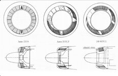
This is my drawing, but it is based on a figure in Calum Douglas' book...
AnnularRadiator.png
From the photos, it looks like annular radiators are at the front, perpendicular to the airflow. I am sure people did it this way, but other people got clever. Note the small air inlet, the large cross sectional area of the radiator, and the small exit, all consistent with Meredith's recommendations.
 
This is my drawing, but it is based on a figure in Calum Douglas' book...
From the photos, it looks like annular radiators are at the front, perpendicular to the airflow. I am sure people did it this way, but other people got clever. Note the small air inlet, the large cross sectional area of the radiator, and the small exit, all consistent with Meredith's recommendations.
The problem was that the concept that Meredith advanced required qute a bit of sophistication in both the inpot flow 'tubes' to minimize chaotic turbulence impinging on the front face of the radiator and a much longer exit run to achieve the desire velocity increase.

Hawker Hurricane was much closer in concept than either Supermarine or Ki-61. The above design will achieve cooling but not desired thrust that Meredith conceptualized. Martin Baker finally figured it out.

Whether by happy accident or genius, Atwwod insisted on the correct replacement of the radiators imbedded into the aft fuselage and Horkey understood how to make it work. That said, it took quite a bit of future tweaking, including consulting with Brit Dr. Shenstone to get working model in NA-73 production, and further efforts to fine tune iteratively to the long standing P-51B/D design.
 
The problem was that the concept that Meredith advanced required qute a bit of sophistication in both the inpot flow 'tubes' to minimize chaotic turbulence impinging on the front face of the radiator and a much longer exit run to achieve the desire velocity increase.

Hawker Hurricane was much closer in concept than either Supermarine or Ki-61. The above design will achieve cooling but not desired thrust that Meredith conceptualized. Martin Baker finally figured it out.

Whether by happy accident or genius, Atwwod insisted on the correct replacement of the radiators imbedded into the aft fuselage and Horkey understood how to make it work. That said, it took quite a bit of future tweaking, including consulting with Brit Dr. Shenstone to get working model in NA-73 production, and further efforts to fine tune iteratively to the long standing P-51B/D design.
I have a copy of Meredith's report here. I am trying to wrap my head around all the math. The concept is that you bury the radiator inside the aircraft, and feed it through a much smaller duct. You reduce the frontal area of the aircraft. The air slows down as the duct expands, and it flows through the radiator at lower speed, reducing drag further and probably improving heat exchange. On the Wikipedia page, there is a comment under Talk that Meredith Effect is pseudo-science, and that the page should be deleted. The recommendation is being ignored. As noted above, I am trying to figure out the math.

At the end of Meredith's report, there is a short paragraph that states that heat rejected in the engine exhaust and coolant radiators can be recovered by converting it to thrust. Most WWII aircraft used exhaust thrust to increase speed by 10-15mph.
 
I have a copy of Meredith's report here. I am trying to wrap my head around all the math. The concept is that you bury the radiator inside the aircraft, and feed it through a much smaller duct. You reduce the frontal area of the aircraft. The air slows down as the duct expands, and it flows through the radiator at lower speed, reducing drag further and probably improving heat exchange. On the Wikipedia page, there is a comment under Talk that Meredith Effect is pseudo-science, and that the page should be deleted. The recommendation is being ignored. As noted above, I am trying to figure out the math.
You have the concept correct. The devil is in the details. rhoV1A1=rhoV2A2 is correct in describing the reduction of velocity from intake scoop to the radiator. The challenge is that really turbulent air is coming in and the plenum needs to 'encourage' the flow to behave as 'attached' to the inner walls as it expands - otherwise chaotic and unpredictable flow impinges upon the radiator face, lessening the optimal flow enabling best heat transfer and lower delta P across the radiator.

Ideally there is even flow distribution through the radiator - emerging at constant velocity in a higher energy state at ~ 210-220 degrees F and squeezed to increase velocity to the exit scoop. The longer run of the Mustang plenum vs Hurricane enables the hot flow to convert heated air to higher velocities as the plenum closes to the exit scoop. The Hurricane exist scoop by contrast is very short and not a good design to maximize energy retention before exit.
At the end of Meredith's report, there is a short paragraph that states that heat rejected in the engine exhaust and coolant radiators can be recovered by converting it to thrust. Most WWII aircraft used exhaust thrust to increase speed by 10-15mph.
It's real. What is True is that while cooling drag was close to zero (combined pressure and friction drag of the inside Plenum and radiators), it probably nevered achieved actual net Thrust over total drag of the cooling system until the P-51H at very high power settings and improved radiator design.

Exhaust is real and easily calculated with right sets of data but totally different from Meredith effect applied (correctly) to imbedded coolant (and oil) radiators.
 
This is my drawing, but it is based on a figure in Calum Douglas' book...
From the photos, it looks like annular radiators are at the front, perpendicular to the airflow. I am sure people did it this way, but other people got clever. Note the small air inlet, the large cross sectional area of the radiator, and the small exit, all consistent with Meredith's recommendations.
This is a drum-type annular radiator with the matrix positioned like a drum around the central axis.

The axial-type (?), like the Fw 190D-9 had, had the radiator matrix facing the airflow frontally.
Was the drag of that type higher?
 
This is a drum-type annular radiator with the matrix positioned like a drum around the central axis.

The axial-type (?), like the Fw 190D-9 had, had the radiator matrix facing the airflow frontally.
Was the drag of that type higher?
Without actual wind tunnel data we are all just guessing.
And you need the data from each different installation and at different speeds and air densities (altitudes).
Somebody could do a decent job making a Axial flow Fw 190D-9 type radiator and somebody else could make a hack job of it.
Any sudden turns or angles in duct/s are going to screw things up. You also have a very limited amount of time (space) to slow the air down from around 400mph to 200-250mph (just guessing) get it through the radiator and not only cool the engine but pick up enough heat for the mass of air moving the through the radiator help get the air mass back up to speed before it exits the rear of the duct.
Annular radiators have a bit of problem. They may be able to cool well, They may be able to get the airflow back up to speed although with the short duct that is doubtful, but I don't have a wind tunnel so I don't know. What they don't have is an exhaust path that actually lines up with the direction of flight. It is going to be off by a certain amount of degrees and then we can argue about thrust vectoring, assuming there was actually any real thrust.
More than a few people screwed up normal radiator installations in the late 30s and early 40s just getting the engine to cool off, let alone trying for thrust and this was 3-6 years after Meredith published his paper. Bell with the XP-39 was a classic case of poor coolant duct design, AND poor oil cooler duct design AND poor intercooler duct design all at once.
 
This is a drum-type annular radiator with the matrix positioned like a drum around the central axis.

The axial-type (?), like the Fw 190D-9 had, had the radiator matrix facing the airflow frontally.
Was the drag of that type higher?
I interpreted Calum Douglas' drawing as an Fw190 or a Ta152. An axial radiator does not increase the frontal area of the aircraft (good), but it does nothing clever with the airflow (bad). In my figure, we can see that the duct expands towards the radiator, and that the radiator has a large cross-sectional area. The air exhaust may not be so effective.

Look for drawings of the de Havilland Mosquito's radiators. Those were considered to be clever too.
 
exhaust is real and easily calculated with right sets of data but totally different from Meredith effect applied (correctly) to imbedded coolant (and oil) radiators.
And this is also not quite as simple as it seems as you well know. The exhaust thrust calculations and pipe/nozzle dimensions can only be exactly right for one mass flow (fuel and air masses) at one altitude (back pressure) and one airspeed. Most of the time it is a compromise. Now decide how much of a compromise.
P-40s had their exhaust stacks cut off (shortened) in the field for a bigger nozzle area when they were approved for WEP. When you are trying to make 30-40% more power with higher boost you have to get the higher mass of exhaust gas out of the engine. Operating at anything less that WEP meant the exhaust gasses were exiting at lower velocity which means less thrust (mass times veleocity). Somebody may know in some test buried in time or lost.

There are lots of reasons why engineers spent years in school learning about this stuff. The Basic formula's may not be that hard but applications are not simple and trying to figure out all (or at least some) of the possible combinations is what may be the difference between success and failure.
 
I interpreted Calum Douglas' drawing as an Fw190 or a Ta152. An axial radiator does not increase the frontal area of the aircraft (good), but it does nothing clever with the airflow (bad). In my figure, we can see that the duct expands towards the radiator, and that the radiator has a large cross-sectional area. The air exhaust may not be so effective.

Look for drawings of the de Havilland Mosquito's radiators. Those were considered to be clever too.
 

Attachments

  • Screenshot_20260603_000118_Chrome.jpg
    Screenshot_20260603_000118_Chrome.jpg
    81.5 KB · Views: 28
I interpreted Calum Douglas' drawing as an Fw190 or a Ta152. An axial radiator does not increase the frontal area of the aircraft (good), but it does nothing clever with the airflow (bad). In my figure, we can see that the duct expands towards the radiator, and that the radiator has a large cross-sectional area. The air exhaust may not be so effective.
the "trick' is to get close to the same airflow through the radiator from front to back. If the air hits the rear of the duct before it turns upward a lot of the radiator at the front is getting bypassed. At high speed the air is going to have momentum (in reverse?) and getting it to move outward through the radiator matrix in a uniform manner is not going to be easy. Turning the air a second time to flow rearwards to the exit area is also a bit tricky. Maybe the exhaust area of the cowl is in a low pressure area? Air flow over that area of the cowl in faster than the flow right before it? Change in diameter of the cowl? And this helps but only at certain speeds?

Think of mass, as in hundreds of pounds/kg of air per minute flowing through the duct and radiator matrix. Unless things (flow) are really smooth you are going to get eddies/swirls and these can disrupt flow in a wide portion of the duct.
 
the "trick' is to get close to the same airflow through the radiator from front to back. If the air hits the rear of the duct before it turns upward a lot of the radiator at the front is getting bypassed. At high speed the air is going to have momentum (in reverse?) and getting it to move outward through the radiator matrix in a uniform manner is not going to be easy. Turning the air a second time to flow rearwards to the exit area is also a bit tricky. Maybe the exhaust area of the cowl is in a low pressure area? Air flow over that area of the cowl in faster than the flow right before it? Change in diameter of the cowl? And this helps but only at certain speeds?

Think of mass, as in hundreds of pounds/kg of air per minute flowing through the duct and radiator matrix. Unless things (flow) are really smooth you are going to get eddies/swirls and these can disrupt flow in a wide portion of the duct.
The Mustang's ducts were not straight either. I have seen the patent for Townend's ring. There is no math. I am guessing that the guy had a wind tunnel, and that he messed with configurations until he got the eddie's he wanted. I suspect that NACA cowlings were similar.
 
I suspect that NACA cowlings were similar.
Which NACA cowlings?
NACA cowlings of 1929 were a lot like Townend rings only longer, and more of a lip.
By 1933-34 they had interior baffles between the cylinders and between the cylinder heads and the cowling to force the air through the fins. By 1935 they were starting to put adjustable flaps on the back of the cowl to adjust the airflow through the cowl at different speeds and throttle settings.
When somethings started out it didn't take much to improve on what they had.
-special-exhaust-ring-and-cylinder-helmets-2M9730K.jpg

Looked good until you saw what really worked.
 
Which NACA cowlings?
NACA cowlings of 1929 were a lot like Townend rings only longer, and more of a lip.
By 1933-34 they had interior baffles between the cylinders and between the cylinder heads and the cowling to force the air through the fins. By 1935 they were starting to put adjustable flaps on the back of the cowl to adjust the airflow through the cowl at different speeds and throttle settings.
When somethings started out it didn't take much to improve on what they had.
View attachment 881688
Looked good until you saw what really worked.
Given that NACA cowlings were the product of guys playing with wind tunnels, and given the different engines they were used on, I would expect them all to be quite different from each other. This is the sort of thing that keeps improving with practise.
 
The Ki-84 had little room for growth because its short legs forced a small prop, and I doubt a 5 bladed prop would have helped much in harnessing the power, as sweep efficiency is a big loss in smaller diameters.

That is the magic of narrow track gears: Even with short legs and deeply cranked wing dihedrals, the prop still clears, as it did in Spitfires. The criticism of narrow track landing gears never shows the slightest understanding of the massive benefits... In the 109 it allowed a forward gear position that gave full power for short field sideway take offs, straight into the wind, without 4 guys holding the tail down... The Spitfire could not do that but it should have. Yes the 109 had a lower tolerance for side winds than most (15 knots vs 25 knots), but it could go in any direction on a wide field...

Those short legs is why the true performance of the Ki-84, as measured by actual Japanese data, is around 395-410 mph top speed and not 427, while the climb rate was about like that of a 190A-8 at 1.58 ATA. Power to weight is irrelevant when your prop cannot deliver the power.

The Ki-84 was always flown with 92 octane fuel and automatic MW-50 when above 425 km/h, so it did not drastically underperform because of poor build quality, as is often claimed. It just could not get much better. And when ferried on delivery it had no MW-50, so it could only reach 425 km/h: This was then used by historians as an example that they were badly built!
 
Last edited:

Users who are viewing this thread

Back