
Merlin P-51 (B-D/K and XP-51F/G and P-51H) supercharger intake size

Ad: This forum contains affiliate links to products on Amazon and eBay. More information in Terms and rules

BarnOwlLover

Staff Sergeant
1,075
459
Nov 3, 2022
Mansfield, Ohio, USA
Anyone have any info on the differences in size (and reasoning for it aside from drag reduction) between the original Merlin Mustangs vs the lightweight/lightweight based P-51s? Been looking at photos of those items and wondering if anyone can offer up details on the differences.
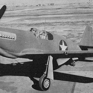
 
Another thing I noticed is that very early B model (prototypes) had an intake about as small as it was on the F/G/H:

main-qimg-fb3bdc0bdaa1e68f69f024b1d9ba28f4.jpeg


img066 - 副本.jpg
 
I'm assuming they started with something similar to the Spitfire intake and then extended it (for aerodynamics?) to the spinner. After all, the Seafire (? 47 I think) also had a pulled/pushed intake to the spinner. Actually, the more interesting question is that the British put a large cooler (for a 2-stage compressor) in the nose of the Mustang X. Where did NA cram it?
 
The B/D Merlin model had it as in your diagram.

The question was about the XP-51B (and both ? are reworked A model (hence shallower fuselage).

But after a little study of the photo, it seems to me that the whole part with the (characteristic for Mustang) intake under the fuselage is deeper, i.e. lower. That is, both intakes are more or less in place of the later models, but the structural lowering of the wings has not yet been made. That's why both intakes stick out more and are not hidden in elegant lines like on the final B model.
If I'm right.
 
And if I were to be careful and read what it says, I would see that in the first photos it is the XP-51F.🥴

But at least I think that I clarified (to myself) the appearance of the XP-51B.

It is actually interesting that the F has a similar solution like the B model.
 
Last edited:
The question was about the XP-51B (and both ? are reworked A model (hence shallower fuselage).
The XP-51B are based off two of the NA-91 P-51 (no suffix) Mustang - Mustang IA in RAF service, from the 58 retained by the US out of the order of 150 originally intended for the UK. Basically it was a proof of concept and involved the fitting of the Merlin with the deeper lower cowling to accommodate the Merlin's updraught carburettor arrangement and a revised deeper radiator assembly to include a larger radiator assembly and the intercooler. At that stage the deepening of the fuselage under the cockpit which moved the wing down about 4 inches and the rework of the lower fuselage profiles had not taken place as for the final design for the production P-51B.

The NA-99 P-51A Mustang - Mustang II in RAF service was two production models of Allison engine Mustang after the NA-91 P-51, with the NA-97 A-36A Mustang in between.

The Rolls-Royce Mustang X conversions were based off the Merlin engine 'power egg' installation as fitted to the Merlin engined Beaufighter and the Avro Lancaster, where the radiators and intercoolers were all mounted under the engine at the front. Effectively the original NAA radiator assembly under the fuselage was largely redundant in that configuration. It wasn't optimal but it worked. But it served its purpose to get the required baseline performance figures to confirm that fitting the Merlin to the Mustang airframe would likely produce a fighter aircraft with superior higher altitude performance. The Rolls-Royce Heritage Trust has a very good book about R-R's engine projects with the North American Mustang, including a number of chapters on the Mustang X project and the co-operation between R-R and NAA on the Merlin engine Mustang.

If you want a better understanding of the development of the Merlin engine Mustang from the Allison engine Mustang, suggest you get a copy of Bill Marshall & Lowell Ford's book.

P-51B Mustang Bastard Stepchild Marshall & Ford Cover.jpg
 
Last edited:
re
Actually, the more interesting question is that the British put a large cooler (for a 2-stage compressor) in the nose of the Mustang X. Where did NA cram it?
The diagram below shows the 2 separate (inter/after-cooler and engine) cooling systems. The actual after-cooler radiator and the associated inter/after-cooler coolant system header tank is located in the engine compartment at the upper-rear of the engine block, just before the intake manifold. While the actual inter-cooler is the volume inside the supercharger housing between/around the 1st and 2nd stage impeller housing (shown a bit crudely here as a simple ring) with the primary after/inter-cooler radiator sitting alongside the engine coolant radiator in the under-fuselage doghouse..

P-51B:C:D cooling system copy.png


I have not run across any measured numbers for how much the intercooler reduces the charge temperature between the 1st and 2nd stage, I have run across general statements that the combined inter-cooler and after-cooler system reduces the temperature about 100°C overall. When I run the numbers I get a minimum necessary reduction of about 55°C at 3000 rpm at 15 lb boost at sea level in low gear, and about 95°C at 23,000 ft in high gear. I think (per my numbers) the inter-cooler ring reduces the temperature by about 25°C with the after-cooler doing the rest of the work.

The manual says 4.5 USgal coolant for the inter/after-cooler system, and 16.7 USgal for the engine cooling system.

Make sense?
 
Last edited:
No doubt the "inter-after" cooler is mainly an after cooler.

The intake manifold radiator is clearly located between the two-stage supercharger and the cylinder heads. So it is "after". But... yes, there is a little cooling effect between the two integrated stages, but the coolant is mainly refreshing the crankcase more than the airflow !

In US practice with two separate superchargers—the first one exhaust-driven and the second gear-driven—placing an intake manifold radiator between these two creates an undeniable and true "inter"-cooler.
 
Last edited:
?

Please see number 4 (labeled "supercharger intercooler") in the diagram above. The diagram does not show the actual supercharger impellers, but the blue cooling ring is located in between the 1st stage impeller/plenum chamber and the 2nd stage impeller.

The image below shows the cooling ring in between the 1st and 2nd stage impellers and abutting the plenum chamber/air passage between the 2 stages. (I added the blue color fill in order to show the location.)

Merlin 60 series inter-cooler copy.jpg

If this part of the arrangement is not an inter-cooler, what should it be called?
 
Last edited:
Seems that the British are doing everything they can to complicate things for us !

Nevertheless, I maintain that the cooling provided by the system is primarily due to the radiator, as its heat exchange surface area is incomparably greater than that of the casing walls separating the two stages.

Not to mention that the gas velocity is necessarily lower there, which promotes heat exchange.

So I still believe that the whole thing is mainly an aftercooler, as I said.

But to be strictly accurate... a system that's "a little" inter and "a lot" after. And perfectly efficient, but that goes without saying !
 
Aside from all the internal stuff on real stuff (but it's nice to know), creating a scale model of the XP-51B isn't like you can just take an A (or no suffix) model and put the engine fairing of a B(D) model (because it's too "deep") nor the under-fuselage intake because it's too shallow. And B have to "low" wings. Maybe it's a start but no way to make a simple conversion. 🤔
 
Aside from all the internal stuff on real stuff (but it's nice to know), creating a scale model of the XP-51B isn't like you can just take an A (or no suffix) model and put the engine fairing of a B(D) model (because it's too "deep") nor the under-fuselage intake because it's too shallow. And B have to "low" wings. Maybe it's a start but no way to make a simple conversion. 🤔
AI does it.
 

Users who are viewing this thread

Back