P-39 Airacobra Horizontal Stab LE?

Ad: This forum contains affiliate links to products on Amazon and eBay. More information in Terms and rules

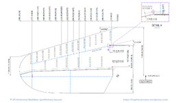
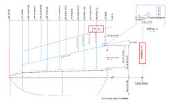
I am working on the Horizontal Stabiliser layout for the Bell P-39. I ran into a few problems with getting the layout dimensions to ensure alignment with the jig positions on the rear fuselage...that is more or less sorted but I do have an issue with the LE setout. The HS layout refers to drawing #12-210-501 which is not in my archive. Can anyone help me establish the location of the LE from the Elevator Hinge and the angle relative to the same...any further information on the curved tip would be welcome?. I should note there is a dimension (58.58") quoted in an old NACA Wartime report but unverified.
 

Attachments

  • P-39 HS LE.jpg
    P-39 HS LE.jpg
    101.6 KB · Views: 35
Last edited:
Hugh: According to the reference that I looked at, the drawing was microfilmed and is out there somewhere. If you build up the stab with the front spar and the ribs, and couple the data off of 12-820-001 drawing, you should be able to back into some pretty close numbers for now. There are number of shops that have restored P-39's and it might be worth contacting them to see if they have the -501 drawing.
 
Thank you. I did look at the fillet layout which more or less agrees with the NACA report location. I emailed the Finnish AF Museum and Niagara Aero Museum, both of which have P-39s. I shall endeavour to also contact some of the restoration companies as you suggest and hopefully, they may be able to help.
 
Thank you, I already subscribe. I have determined an approx sweep angle and location based on the best available data. The sweep angle comes in at roughly 16.7 degrees. If there is an opportunity to verify these dimensions I will endeavour to update this post.
 

Attachments

  • P-39 LE Stab.jpg
    P-39 LE Stab.jpg
    120.2 KB · Views: 24
See if the later models used a different horizontal stab. If so they may have done a more detailed drawing - try 14-210-501 which is interchangeable on all early models.
26-210-001 used on N and later is not interchangeable with the 14- one but I do not know why, may help
 
Drawing #14-210-501 refers back to the drawing in question #12-210-501. There is another variation on the stabiliser drawing #12-211-001. Neither the former #14-210-501 nor the latter #12-211-001 contain the information I need to verify the information that would undoubtedly be noted on #12-210-501. Overlaying the known layouts on the CAD drawings shows that the layout I have is about right but it bothers me that it is probably not exact.
 

Users who are viewing this thread

Back