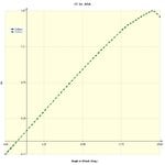
P-40E Flight test data

Ad: This forum contains affiliate links to products on Amazon and eBay. More information in Terms and rules

Kai Lae

Recruit
4
0
Aug 9, 2017
Pretty much posting this because I don't know where I should be looking that I haven't already. I'm looking for some very specific data about the P-40E regarding it's wing design, specifically, the determination of it's coefficient of lift (CLMax). The only data on this that I have been able to find that contains information that can be used to determine this is a RAE Boscome Down test. Unfortunately, the derived lift coefficient from these tests is unusually high, to the point that it casts doubt about the validity of the data collected. What I want - really, really want - is a Curtiss-Wright document that provides similar data, either collected during initial flight testing, or at some later date. A document that just lists what the engineers were trying to achieve with regards to this would also be great.

I've actually tried contacting Curtiss-Wright and got nowhere (I'm wouldn't be surprised if some intern read my inquiry and didn't have any idea what to do with it). If someone had contact information where I could take my questions in a more productive area that would be also great.

I have not attempted to get NASM data simply because all I have is vague descriptions on what is in certain boxes and no guarantee that it would contain anything useful. If I lived close I'd just drive over there and copy the whole damn thing but that's not an option. I'm also interested in any other data about the plane that could be useful in similar areas, such as the design critical AoA or perhaps time to reach max speed from X starting speed (computation of acceleration and possibly overall drag).

Thanks for any light you can shed on this. Old records can be hard to find, but this hard is very frustrating.
 
My analysis shows a Clmax of 1.67 at 23.5° for the 3d wing. This is at 90 MPH EAS, or the stall speed corresponding to a weight of 8165 lbs. Airfoils are NACA 2215 at root and 2209 at tip, no twist. Program used was Multisurface Aerodynamics by Hanley Innovations. I think you'll find that very reasonable, given stall speeds in the manual ( without corresponding weight ).
 

Attachments

  • P-40_wing.jpg
    P-40_wing.jpg
    37.8 KB · Views: 287
Thanks for the info. This tracks closely to previous information that I have seen. The problem is that (as I understand it, my background is electrical) a power off CLmax of between 1.2-1.4 is typical. Knowledgeable people have told me that a CLmax of nearly 1.7 is the equivalent of finding a flying unicorn. This is why I'm been trying to find corroborating data past that which has been seen in the RAE report (I'd love to find a US report that basically says the same thing, as that would help seal the deal). Does anyone know if such a thing exists or can be found?
 
Who are these "knowledgeable people" and where did they get their information? NACA report 460 shows 1.60 for NACA 2212 airfoil at 3.3 Rn ( not very fast ). The Spitfire uses the same airfoil section, albeit a couple of percentage points thinner. If you can find data for the Spitfire, that would be close enough for the P-40 as well.
 
It's an argument over P-40E performance characteristics, specifically, over the ability of the aircraft to turn. My background is basically electrical engineering, so I find it difficult to make what I believe the case that the aircraft should be able to outturn most if not all types of Me-109, at least in the horizontal plane. There are a few aeronautical engineering types who are telling me what I posted before; I obviously lack the knowledge to know one way or the other and have been relying on what they are telling me. What I've been told is that 1. That CLmax is beyond plausible, 2. There are no records that seem to be easily available that show the 2215 (?) that you can refer to as a reference and the 2212 - which you can - is is not exactly the same and therefore not definitive.

Thus I've been searching in vain for corroborating documents, because so far there's not enough to hit them in the head to make them agree lol. Confirmation bias is a thing and overcoming it can be difficult.
 
NACA Data - 16 Jan 43
P-40 Airplane (Air Corps No.39-160)

Span: 37 feet 3.5 inches
Area: (including wings and fuselage): 236 square feet
Airfoil Section: NACA 2215 at root and
Airfoil Section: NACA 2209 at 197 inches from fuselage
Aspect Ratio: 5.89
MAC: 81.6 inches
Taper Ratio: 2.3 to 1
Dihedral (LEW): 6 degrees
Incidence: 1 degree
Sweepback: 1 degree 19 minutes
 
Hmm, well these "aeronautical engineering types" need to come to the table with sources, or else they have nothing. Here's a little bit more history about NACA airfoils. I refer to report 460 again, published in 1933. See page 348 for a description of the 2R1 airfoil, used on the 109. I quote, "...airfoils having reflexed mean lines may be of questionable value because of the adverse effect of this mean line shape on the maximum lift coefficient." They tested 1.53 at Reynolds Number 3.26M. The N.A.C.A. observed that airfoils with the camber forward of 20% chord had superior characteristics and so they developed the 23012 ( see reports 530 and 537 ).

With the 109, you're opening a can of worms, because of the slats. While they would normally increase the maximum lift ( if they were full span ), in the case of the 109, they soften the stall and don't necessarily increase maximum lift, since the inboard section would be stalled while the outboard section would not. I appreciate what you are looking for, as someone who has been researching these subjects for near 20 years. Even if you find what you are looking for, you will need just as definitive information for the 109 as well, for any comparison to be meaningful. Good luck with that! Unfortunately, my software doesn't allow me to model slats accurately or I would do the analysis for you.
 
It's OK to derive CLmax from the clean stall speed. Then for any given speed you can work out how many g you can pull. You can use the cruise CL to derive the induced drag, taking reasonable approximations for the efficiency factor, say 0.9 for a typical WW2 fighter monoplane. You get the total drag from the power, prop thrust and weight and the induced drag from the appropriate formula, giving the form drag (it has various names but its the part of the drag which varies with rho V^2) by subtraction. From these numbers you can approximate the total drag and therefore top speed, climb, all sorts within limits of the approximation. Yes, even ideal turn performance. But not in real combat, where other factors come in.

One result of all this is going to be that if you have need a high CL, you will tend to have a large CDi, and if you are using that in a turn it means a lot of drag, hence deceleration and/or loss of height. With the 109's slots it means good instantaneous turn but not too good sustained, the slats are like parachutes. But the higher AoA means you can maybe get a firing solution.

(For rule of thumb comparison, use span loading for a pointer to how hard the wing has to work to deliver lift.)

A span efficiency of 0.9 is probably high, but that's merely quibbling. I think, but can't be sure without the design documents, that the Bf109 had slats added because they expected the outer wings to stall first, which is exactly the opposite of what's needed for good stall departure characteristics. They may even have been added during early flight testing because the pilots reported unacceptably bad departure characteristics. Trailing edge flaps, because they increase camber, will unload the outer part of the wing, so the automatic slats would have been added because of behavior flaps up.
 
For the purposes of the discussion, the characteristics of the 109 are basically irrelevant. That, is actually, a completely different can of worms that I don't want to get into right now. The topic is confined to the capabilities of the P-40, against stipulated characteristics of the 109. I as stated, think the P-40 is being underrated. The only data that I've ever seen on measured turn performance was done by the russians who timed it at 19s, but since they did not record either the power they used nor the altitude they did their testing at it's not useful (unless someone knows this). I should also note that the debate is over the simulated flight model in a combat flight sim.

The report 460 referenced above sounds like I should have a look at it. How would I get that? Perhaps a better question is would I understand it.

The CLmax that you would find in WW2 fighter aircraft has been told to me as in the range above. The number that is apparently used in the information given is roughly about in the 1.32 range. Various other aircraft have also been listed in that area, such as the 190 (1.35) etc. What started me asking questions was the very poor turn performance of the simulated aircraft, plus the fact that the simulated aircraft stalls at 95 MPH, while the flight manual lists 90. Also, the stall AoA of the plane from the developer's own data sheet is listed at 14 degrees, which is abnormally low.

What I and some others have been trying to do is get data that proves these things are erroneous. The difficulty is that in order for a company to devote resources to change anything, you need really solid data to make your argument. After all, it's not like they intentionally went out to screw the pooch. They believe they got it mostly right the first time. You're asking them to spend time - which is of course, actually, money - to alter it to something else. That's where the challenge has been, trying to find reports - preferably, multiple reports which confirm data sets that other reports have - to make the conclusive argument. I'm very good at troubleshooting and fixing things, but the lack of understanding of another field of engineering makes it difficult for me to know what I need to get, what is important, etc. So, not having tried to ask here before, hey, it might be worth a shot to see if someone can shed some light on this so I can make some progress in putting together a report to submit to the developers.

Thank you for any information you can provide, it's appreciated.
 
I've looked into this sort of thing, and sometimes there are no good documents to reveal the numbers you want. And when you find two sources they can disagree considerably. I don't find a 1.35 CL too low for a flaps-up WW2 fighter. Or 14 degrees AOA (rule of thumb again, AOA in degrees is ten times CL). I remember NACA found the Spitfire V to have a very low CLmax, but it was always known as a good turner.

As a rule of thumb I derive the CL from the manual stall speed, but be aware that the manual is written for a young pilot. The speed refers to the asi reading, not true airspeed. You will find a chart there to correct for position error but that too is only a guide. Having said that, pilots in a turn, in combat, may not be flying up to the theoretical g factor. For one thing there is no reason to expect the 4g speed to be twice the 1g speed, not exactly as the formula would tell you. Controllabity, prop wash, stall warning, all sorts of factors. You are right to suspect if your flight model makes your P-40 a bad turner, it was not, compared to most western contemporaries.

I don't know what resources you have, but a lot of NACA reports are online

. NACA Technical Reports Server (NACATRS) | University of New Hampshire Library

For US machines I recommend 'America's Hundred Thousand,' by Dean


(I'm mostly self-taught, treat all mym utterings accordingly.)
 

Users who are viewing this thread

Back