P-61 Gun-Laying Radar

Ad: This forum contains affiliate links to products on Amazon and eBay. More information in Terms and rules

Imagine a plate sitting on a table. That is your antenna dish. Now imagine there's a small depression in the exact center of the plate in which the point of a tall slender top is spinning. Gyroscopic rigidity in space keeps the top perpendicular to the plate. That is your rotating feedhorn.
I follow you...
Now imagine you can suspend the laws of physics enough to pick up this plate/spinning top assembly and bolt it into an articulated gimbal structure on the front end of your aircraft. This gimbal has powerful little motors that drive the dish left-right-up-a-notch, left-right-up-a-notch, and so forth until it reaches the upper gimbal limit, then repeats the process down to the lower limit and back to level. Since a feedhorn isn't as symmetrical as a top, the beam it projects from the dish at any point in its rotation is not symmetrical around the central axis of the dish. Rotation of the feedhorn causes this asymmetrical beam to form a very slender cone of signal centered on the axis of the dish, strongest on axis and weaker towards the edges. This oprovides the signal strength comparisons that generate the "pointing error" signals used to drive the antenna to put its axis "on target". Once the antenna is "on target", the azimuth and elevation are known and return time provides range.
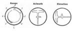
So the higher the error-signal, the more the antenna adjusts until there is none?

This looks a lot like triangulation, but Token mentioned something about measuring errors through amplitude and phase changes (which I assume to be constructive/destructive interference effects).
 
Those are some of the limitations, to be sure. And your look down angle is also limited by your altitude. Without MTI (and these early radars did not have MTI) looking down will show you the ground out at the end of the range trace. The more you look down, for a given aircraft altitude, the shorter you maximum range to track or detect another aircraft will be.
Because it eventually pings the ground...
I think you are using resolution cell incorrectly though. The resolution cell is the time occupied by the radar pulse. It is a moving space defined in depth by the duration of the pulse and in width and height by the beamwidth of the radar. The resolution cell is the area where a radar can detect a target is present but cannot resolve the number of targets present in the cell. And it has nothing to do with maximum range.
Oh, I figured that if an aircraft was a sufficient distance from the ground, it would be distinct from it, if close enough, it would blend in.
Errors are how the radar knows where the target is. Yes, you want to keep the errors as small as possible, but to do this you must first find the errors, so you can counter or null them. Every track has errors, no track is perfect, so you want to make the errors as small as possible.

The Conical scan is how the radar, in this case, derives the errors to know what direction to drive the antenna, so as to null the errors.
Which is a negative feedback loop...
Kind of like this, only substitute target track for missile:


View: https://www.youtube.com/watch?v=F4Dvc1NrZJI
Boy, that's a tongue-twister and I'd probably have to draw it out to really make sense of it (some things I'm better with visually, some things audibly). Something like a decade or more back, I remember something similar in nature being mentioned about navigation systems.
The Palmer scan is not better at anything, it is simply the combination of two different scan types at the same time. In this specific application the Conical scan is required to track, the Raster is required to search. When the radar has both types of scans active at the same time it is called a Palmer scan. The radar cannot both scan and track at the same time, it is one or the other.
Oh, okay
So while searching, or scanning a large volume of space, it is using a Raster scan, it just so happens the beam also has a Conical scan at the same time. While tracking the radar stops the Raster scan, stares at the target, and uses its Conical scan to derive tracking errors.
I think I got it...
For a bidirectional Raster scan, which by definition changes direction for every bar of the raster, you must overcome that inertia, no matter how small or large it may be. For a Helical scan there is no need to overcome anything except friction, the antenna just goes around and around in the same direction at the same rate, stepping up at some point in each revolution. A unidirectional Raster may do the same thing as a Helical, and have no inertia to overcome, or it might stop and retrace, having to overcome inertia each stop.
Could a palmer scan simply stop once it covered a certain zone that would radiate the plane? It sounds silly, but from a purely academic standpoint, it is interesting...
No, the portion of the antenna mechanism that rotates the antenna and grossly moves the beam around in space in elevation and azimuth is unrelated to the skewed feed that provides the Conical scan.
I'm not sure I really grasp this...
A fixed feed antenna, like the SCR-720, just stares (with its beam) straight ahead of the dish. The device the antenna is mounted on (often called a pedestal) then moves the beam around in space, in the case of the SCR-720 in a Helical fashion (360 degrees of rotation, step up, 360 degrees of rotation, step up, etc), in the case of the APG-1/2 in a Raster.

Completely separate from that is the Conical scan. It rotates the beam of the antenna in small circles out in front of the antenna, independent of how the pedestal moves the dish. To do this it is intentionally skewed, mechanically, so that the beam does not go out directly ahead of, and on axis with, the dish. It goes slightly off center of where the dish is looking.
Just the feed (which I assume is the pointy thing at the middle of the dish) spins round and round and the dish sits still? Up to this point, I thought the whole dish spun 'round and 'round.
More often when you want to allow both Conical scan (a spinning off boresight axis beam) and on boresight axis fixed beam operation you don't use a mechanically skewed feed assembly. Instead you wobble the dish itself to create the circular beam motion about the boresight axis. This would result in a nutating beam.
The whole dish spins in this set-up...
 
This looks a lot like triangulation, but Token mentioned something about measuring errors through amplitude and phase changes (which I assume to be constructive/destructive interference effects).


I said either amplitude or phase changes, not amplitude and phase changes. I also said in this example it is just Amplitude changes.


A tracking radar will produce the elevation and azimuth errors by either amplitude changes or phase changes, depending on the system design. I am pretty sure the APG-1/2 used amplitude changes.


It is by comparison of the amplitudes of the target when the Conical scan is in varying locations that does this. If the target is stronger when the conical scan is pointing right and weaker when pointed left then the antenna boresight needs to be driven to the right until the target is equal in amplitude when the Con scan is at both left and right.


T!
 
Oh, I figured that if an aircraft was a sufficient distance from the ground, it would be distinct from it, if close enough, it would blend in.


Assuming you are talking about the target aircraft and that sidelobe power does not cover the target (the lower sidelobe will have a shorter path, slant range, to ground), then yes.


Could a palmer scan simply stop once it covered a certain zone that would radiate the plane? It sounds silly, but from a purely academic standpoint, it is interesting...


The Palmer is simply a combination of a Raster scan, moving the radar beam grossly for the search function, and a Conical scan, moving the beam (not antenna) for fine detection of target position.


Instead of mechanically stopping the moving antenna (for the Raster) and moving feed (for the beam) it would be simpler to just inhibit the transmitter in areas it might get self reflections. This is what the SCR-720, with its continuous helical scan which pointed back towards the aircraft a lot of the time, did.


I'm not sure I really grasp this...

Just the feed (which I assume is the pointy thing at the middle of the dish) spins round and round and the dish sits still? Up to this point, I thought the whole dish spun 'round and 'round.

The whole dish spins in this set-up...


Yes, in the case of the SCR-720 and the APG-1/2 the feed is that thing pointing out of the center of the parabolic dish.

Separate out the two functions and tasks in your head. There is a Search function, and there is a Track function. They require different techniques and must be addressed individually. In the specific case we are talking about the Raster scan exists for search, the Conical scan exists for track.


When talking about spinning and turning it can get confusing. Lets call azimuth, right and left, the X axis, call elevation, up and down, the Y axis, and call range the Z axis.


For the search requirement you need to grossly move the beam in space to cover a relatively large volume. In this case you do it by moving the entire antenna. The dish "points" in both elevation, Y axis, and azimuth, X axis, to cover the desired volume of space. The SCR-720 did this, with its Helical scan, by spinning the dish structure around and around, continuously, in azimuth, or the X axis, with steps in the elevation, or Y axis. The APG-1/2 apparently used a bidirectional Raster scan (however I am not 100% sure of that), which requires you to stop at each end of azimuth, or X axis, motion and reverse direction, stepping up or down in the elevation, or Y axis, at each stopping point. The APG-1/2 could have used a Helical scan also, however what little information I can find seems to say it did not.


For the track function you need to finely move the beam in space, just enough to generate track errors so you can center the target. In the case of the Conical scan specific to the APG-1/2 you do this by spinning the mechanically offset feed assembly along the Z axis (other radars may use different techniques to generate the Conical scan). Errors generated by this process then move the antenna boresight, the centerline of the entire dish assembly, in both the X and Y axis to null the errors.


T!
 
I would have thought that the gun laying radar would be shorter range than the search radar, so you would need both?

A gun laying radar has extra circuitry and antenna modifications that allow it to very accurately track one particular target and then present or transfer that data in a way it can be used to provide a firing solution. It is not shorter ranged though it may be necessary to shorten the pulse. for instance a 2 microsecond pulse is nearly 600 meters long and it would need to be reduced (temporarily) to deal with a target only 150m away. A shorter pulse would improve resolution and minimum range a the expense of maximum range.

Modern radar was an invention of the German navy due to the work of Rudolf Kunhold head of the of the NVA (Signals Branch). He had wanted to use active and passive sonar as a targeting device and eventually concluded that Electromagnetic Waves were a better way. This started the German radar effort in 1932.

By 1934 they had a radar that could track a ship to within 0.1 degrees at 8km using a beam about 6 degrees wide. What they did is use 'lobe switching'. They had two sets of dipoles mounted on a mattress aerial and then switched them mechanically to alternately steer the beam left/right 25 times per second. The left/right returns were then presented on a pair of oscilloscope compared till they were equal using optics (half mirrors). Without the lobe switching the radar operator would need to wobble the aerial lef/right to try and achieve a maximum return which would likely be less than 1 degree accurate (17m error per 1000m).

The German Navy rejected this system because it wasted half the antenna area and reduced range slightly and widened the beam so much that other targets were taken in. At time radar power was limited so first generation seetakt was search and range only with gun laying introduced around 1942 when transmission tubes went from 1.5kW to 8kW.

The US Navy entered the war with its ships equipped with this type of radar (with a 15 degree beam width) and the US Army anti aircraft SCR-268 used this technique with an additional aerial for up/down added. The US had very powerful transmission tubes and was likely less bothered by range loss.

The German Navy eventually used a system in which only the receiving side of the antenna was switched around 1942. This didn't waste so much antenna area, didn't disclose the switching pattern to a jammer.

Aiming, in WW2, then involves pointing the aerial at the target and using magslip or synchros to transfer the bearing to the computer and matching the range 'pip' with a mechanical pointer or a electronic one. again to transfer to a fire control computer.

Automatic range tracking would involve setting a timer at the same time the radar pulse is emitted and then comparing the difference of the timer and the radar echo modify the timer to track the target (filtering it to exclude speeds and accelerations that are implausible.

Conical (also called circular scan) was first used with parabolic dishes with Wurzburg C in Feb 1941 whereby an of axis dipole at the focal point was rotated to produce a conical scan. One operator would track range and then the echoes from that range gate would be put through a peak hold and smoothed to produce a sine like wave. A circle can be described as a sine and cosine wave describing the vertical and horizontal axis. The return would be resolved into horizontal and vertical components by orthogonal sinusoidal generators mounted on the dipole mechanism and passed through circuitry (phase detection) which would allow the operator to drive the antenna in the correct direction or if more refined the small currents used to drive dial indicators could be amplified to drive the antenna via servo motors.

AN/APG-4: Was a radar configured as a 500lb bomb used as an air intercept radar of Corsairs and Hellcats. It could also be used for Low-altitude torpedo-release. It didn't have conical scan for tracking but the entire antenna scanned in a spiral for searching. This radar was known as the Mk XIV in British Service.

AN/APG-6: was an improved version and allowed blind fire in which the spiral search scan could be locked into a 15 degree circular scan. I don't think the antenna physically tracked the target but that it locked the range gate on to the nearest target and evaluated the electrical deviations of the returns to provide targeting information within a linear range of say 10 degrees of the cone. This radar was used by the RAF as the Mk.XV. With a radar operator, as was the case on the P-38 or Mosquito its use might be more sophisticated.

British efforts for blind fire radar died with the death of Arthur Ernest Downing who was shot down in a friendly fire incident while developing chaff resistance for the planed for tracking capable AI Mk.IX in 1941. Quite a lot of scientists and engineers died in this type of work. That the death of one man had such an impact is telling of how leading edge this work was and also explains the German difficulties. In general British AI radar sets were American after the Mk VIII because of the shortage of development resources, hence they focused on a few areas such as ground mapping or something that might be very important such as the village in tail radar system.
 
Last edited:
The SCR-720 did this, with its Helical scan, by spinning the dish structure around and around, continuously, in azimuth, or the X axis, with steps in the elevation, or Y axis.

If I am reading you correctly, you are saying the dish spins on its axis 360° around its vertical axis (ie when viewed from above)?

If so, are you sure about that?

http://pwencycl.kgbudge.com/images/S/SCR-720_airborne_radar.jpg
https://www.ibiblio.org/hyperwar/USN/ref/NightFighterRadars/images/P-61Antenna.gif

It looks to me that movement was limited to +/- 90° from straight ahead.

Which would mean it scanned in a similar way to that described below?


The APG-1/2 apparently used a bidirectional Raster scan (however I am not 100% sure of that), which requires you to stop at each end of azimuth, or X axis, motion and reverse direction, stepping up or down in the elevation, or Y axis, at each stopping point. The APG-1/2 could have used a Helical scan also, however what little information I can find seems to say it did not.
 
If I am reading you correctly, you are saying the dish spins on its axis 360° around its vertical axis (ie when viewed from above)?

If so, are you sure about that?

To me it looks like the dish is mounted on forks sitting a 360 degree rotating pedestal, so yes helical scan.
SCR-720_airborne_radar.jpg
 
If I am reading you correctly, you are saying the dish spins on its axis 360° around its vertical axis (ie when viewed from above)?


If so, are you sure about that?


http://pwencycl.kgbudge.com/images/S/SCR-720_airborne_radar.jpg

https://www.ibiblio.org/hyperwar/USN/ref/NightFighterRadars/images/P-61Antenna.gif


It looks to me that movement was limited to +/- 90° from straight ahead.


Which would mean it scanned in a similar way to that described below?


I am reasonably sure of that, yes. I base it on several items, I'll list the reasons I am pretty sure of this below.


The copy of the SCR-720 I had exposure to in the mid 80s did that. Of course, this was installed on a truck instead of an aircraft, and had been modified, however the antenna, antenna mount, and drive system appeared unmodified. This modified system used the original antenna, antenna drive, transmitter, and high voltage supply, everything else (synchronizer, receiver, displays, etc) was replaced / modified / different.


Every description I can find of the SCR-720 defines the antenna as having 2 rates of operation, 360 RPM and 100 RPM, depending on range selection and if the radar is in Beacon mode. Calling the motion rotation and having the speed defined in RPM strongly indicates to me it is a circular motion. A bidirectional raster scan is not described as rotation.


The antenna motion on/off switch on the BC-1150-A (this is the unit of the SCR-720 that turns on the antenna motion and sets the elevation scan limits) is labeled "Antenna Rotation". Further it says (Section II, paragraph 9, line r) when the radar is in a specific mode of operation "the antenna should turn at a relatively low rate of speed". On line t of the same instructions, after some switches are changed, it says "the antenna should turn at a relatively high rate of speed". The use of the term "turn" to me would indicate a circular motion.


The SCR-720 Basic Operating Instructions are here http://www.tokenradio.net/Aviation/SCR720OperatingInstructions.pdf


The type of scan I described, rotate 360 degrees, step up, rotate 360 degrees, step up, etc, etc, is one variation of a category of scans called a Helical scan. This is described in the 1947 MIT Radiation Laboratory Series, Volume 26, Radar Scanners and Radomes, page 8. http://www.tokenradio.net/Radio/SharedFiles/InfoTfer/Vol_26.pdf


In the book "Chance and Design: Reminiscences of Science in Peace and War", by Alan Hodgkin, page 207, it says "the American SCR-720, with a helical scan" when describing the system.


US Patent 2556673, June 12, 1951, in the first paragraph of section 4, says "The helical scanning radar portion which may be of the conventional form, known generally as SCR-520 or SCR-720 or the like". http://www.tokenradio.net/Aviation/US2556673.pdf


And lastly, if you look at the second picture you posted there appears to be enough room for the antenna (model RC-94) to clear the Transmitter and High Voltage sections (those are the two can looking things behind the antenna). Remember to clear these it only needs half of the dish diameter, the RC-94 dish is 29 inches (some sources say 30 inches) in diameter, so there only needs to be about 15 inches or a little more clear behind the antenna.

http://www.tokenradio.net/Aviation/SCR720_antenna.jpg


T!
 
Token, I remember somewhere back in the mists of time reading of a radar system that had two helical scan antennas, one forward and one aft, that rotated in sync with each other, with a PPI scope displaying the forward sweep, then the aft sweep in one seamless rotating beam for 360 degree coverage. I think it might have been some early version of AEW or AWACS. Does this ring a bell with you? Just curious.
Cheers,
Wes
 
I wondered if that was the Wellington AEW.
No this system had two separate antennas, one in the nose and one in the tail. I think it might have had two separate R/T units too, but I don't remember that or the aircraft type either.
Cheers,
Wes
 
Token, I remember somewhere back in the mists of time reading of a radar system that had two helical scan antennas, one forward and one aft, that rotated in sync with each other, with a PPI scope displaying the forward sweep, then the aft sweep in one seamless rotating beam for 360 degree coverage. I think it might have been some early version of AEW or AWACS. Does this ring a bell with you? Just curious.


I don't recall any that had two separate antennas, with separate drives, in sync doing this, or any using a helical scan. However I have seen and worked with a few that where somewhat similar to what you describe. All the ones I can recall used a circular scan, not a helical, and most of these have been back to back mounted antennas on a single barbet / pedestal.


Some used the back beam as an identical sweep to the front beam, just 180 degrees out, resulting in twice the hits on a given target in a given time period. Some used the back beam for other information, such as altitude.


But I will look through a few references and see if I can find anything similar to what you describe.


T!
No this system had two separate antennas, one in the nose and one in the tail. I think it might have had two separate R/T units too, but I don't remember that or the aircraft type either.
Cheers,
Wes

Nimrod AEW3
 

Attachments

  • British_Aerospace_Nimrod_AEW3,_UK_-_Air_Force_AN0999455.jpg
    British_Aerospace_Nimrod_AEW3,_UK_-_Air_Force_AN0999455.jpg
    83.4 KB · Views: 60
  • nimrodaew-9.jpg
    nimrodaew-9.jpg
    45.6 KB · Views: 83
Token said:
I said either amplitude or phase changes, not amplitude and phase changes.
What's a phase-change? I assume it means interference effects...
It is by comparison of the amplitudes of the target when the Conical scan is in varying locations that does this. If the target is stronger when the conical scan is pointing right and weaker when pointed left then the antenna boresight needs to be driven to the right until the target is equal in amplitude when the Con scan is at both left and right.
I think I grasp what you're saying
Assuming you are talking about the target aircraft and that sidelobe power does not cover the target (the lower sidelobe will have a shorter path, slant range, to ground), then yes.
Well, I was thinking if the range of the target plane was far enough from the ground that it would appear as a different target than the ground, much like how two planes flying very close appear as one, but once they get far enough...
Instead of mechanically stopping the moving antenna (for the Raster) and moving feed (for the beam) it would be simpler to just inhibit the transmitter in areas it might get self reflections. This is what the SCR-720, with its continuous helical scan which pointed back towards the aircraft a lot of the time, did.
Okay, that works
Yes, in the case of the SCR-720 and the APG-1/2 the feed is that thing pointing out of the center of the parabolic dish.
Gotcha...
Separate out the two functions and tasks in your head. There is a Search function, and there is a Track function. They require different techniques and must be addressed individually. In the specific case we are talking about the Raster scan exists for search, the Conical scan exists for track.

When talking about spinning and turning it can get confusing. Lets call azimuth, right and left, the X axis, call elevation, up and down, the Y axis, and call range the Z axis.

For the search requirement you need to grossly move the beam in space to cover a relatively large volume. In this case you do it by moving the entire antenna. The dish "points" in both elevation, Y axis, and azimuth, X axis, to cover the desired volume of space. The SCR-720 did this, with its Helical scan, by spinning the dish structure around and around, continuously, in azimuth, or the X axis, with steps in the elevation, or Y axis. The APG-1/2 apparently used a bidirectional Raster scan (however I am not 100% sure of that), which requires you to stop at each end of azimuth, or X axis, motion and reverse direction, stepping up or down in the elevation, or Y axis, at each stopping point. The APG-1/2 could have used a Helical scan also, however what little information I can find seems to say it did not.

For the track function you need to finely move the beam in space, just enough to generate track errors so you can center the target. In the case of the Conical scan specific to the APG-1/2 you do this by spinning the mechanically offset feed assembly along the Z axis (other radars may use different techniques to generate the Conical scan). Errors generated by this process then move the antenna boresight, the centerline of the entire dish assembly, in both the X and Y axis to null the errors.
Ok
 
ju88_fug202.jpg
fug212.jpg
th.jpg


Blind fire tail guns such as "Village Inn" tail radar used on the Lancaster would I think have not been a success. Likewise for the tail gun radars the US had for the B-24,B17 and B-29.

This is because the same technology possible also made a bigger, more accurate longer range radar in the fighter possible and the fighter is better armed.

Little known is that the Germans deployed a small number of FuG 211 and FuG 215 blind fire radars in combat in 1942. These were known as "Pauke A" and about 10 were produced and trialed in combat. These had an accuracy of 0.5 degrees within +/-10 degrees of forward. The reason they were not deployed in greater numbers is likely because of the IFF (Identification Friend or Foe) problem which confounded everyone and that they get caught up in the frequency changes needed in 1943 to overcome windows. You had to fly up close and get a visual. For the Nachtjagdt the rules were if it had 4 engines its not ours so shoot it down. Proper airborne IFF didn't reach the Luftwaffe but for a few "Neuling" equipped Me 262.

Above is a picture of the early FuG 202C1 Lichtenstein radar mounted in a Ju 88C. It operated at 490Mhz (60cm)

The small aerial in front of the 16 part (4 by 4) array is the dipole from which the signal radiates, the rear antenna is the 'reflector' which is placed 1/4 wavelength away. it reflects the signal forward and is spaced such a way that the reflection constructively interferes with the dipole to increase directionality. Further forward directionality is promoted by the array interference pattern.

By using a rotating switch wave delays were switched in to the dipoles steer the beam alternately left/right then up/down. By comparing the relative strengths of the returns the position could be determined quite well.

This is what the radar operator saw; Below are the radar traces.

The scope on the left is a j scope and shows the range of the target aircraft around its circumference. It is somewhat superfluous in that the other scopes also contain range information. The scope in the middle shows whether the target is to the left or right (in this case the right return is heaviest so the target is to the right) and the scope in the right shows if the target is high or low, in this case high. The big pulse at the end is the ground return.
th.jpg


By evaluating the deviation electronically, rather than visually, the Luftwaffe was able to obtain 0.5 degrees within +/-10 degrees of center. This is a 0.87m error every 100m and probably good for attacks up to 200m away. 200m was certainly the attack range they envisioned.

This was all updated 25 times/second. It was in many ways superior to allied mechanically scanned radar which took many seconds to scan and had equally abstract displays.. The narrow beam of allied microwave radar however made it less susceptible of receiving jamming energy.

The Germans (Telefunken) could have switched in a wider range of delays but left/right/up/down was sufficient.

If the Germans had of replaced their 60cm 1.5kW transmitter with a 15cm 5kw transmitter (which they had by way of the Telefunken LD7 disk triode) and used a more complicated switch pattern 4 left.right and 4 up down) they would have had a phased array radar that could have fitted in a dome.

Somewhat astonishingly the Germans placed their 490MHz 60cm Pauke A radar in a 70cm dish to produce a 57 degree wide beam that could be scanned to track a blind fire solution as an alternative to the array.

FuG 222 "Pauke SD" was a project using 9cm radar, I think using non magnetron sources. Three were built. In addition the FuG 247, a 3cm radar in the lab stage was to be blind fire capable. The FuG 240N3 radar (9cm) deployed on 25 Ju 88G7 aircraft was not blind fire capable but the FuG 244 and FuG 245 (3cm fire control radars from different manufacturers) certainly had some. These radars incidentally found themselves integrated into quad 20mm FLAK and were called "Rettin"

These latter radars injected the firing directions into either the EZ42 or EZ45 gyro 'reflector sight' which had been modified to take inputs from Toss bombing computers or the blind fire computer (Elfe) to deflect the cross hairs appropriately. It was hope to put the signals straight to the auto pilot.

Apart from guns the intention was to use the R100 rocket, a 250mm 10 inch rocket with a proximity fuse to be fired from 1.2km. About 25 were test launched before the end of the war.

Hence tail gun blind fire radar would be outperformed the night fighters radar and weapons.
 

Attachments

  • th.jpg
    th.jpg
    5.5 KB · Views: 75
Last edited:
Blind fire tail guns such as "Village Inn" tail radar used on the Lancaster would I think have not been a success. This is because the same technology that made this radar and the equivalent in the B29 possible also made a bigger, more accurate longer range radar in the fighter possible.

Not sure that the Village Inn system could be termed "blind fire".

And the supposition that the system would not work because of advances in enemy fighter radar is, IMO, false.

The range of the turret mgs remained the same - and was similar to the guns of the attacking aircraft. If the attacking fighter had weapons with greater effective range then the radar may have allowed it to stay out of range of the defender's guns - with or without Village Inn gun laying radar.

The advantage of the Village Inn system is that it calculated most of the parameters for the gunner, so the likelihood of a hit was enhanced.

The B-29 did not use a Gun Laying Radar system - at least not in production versions. It had remotely operated turrets with computing gun sights.
 
What's a phase-change? I assume it means interference effects.
You need to brush up on your basic electronics, especially wave propagation. It can't be explained simply and unconfusingly without a lot of illustrations, which I can't do on this phone. Essentially what it means is the return wave is not perfectly in sync with the transmission wave. But there's a lot more to it than that. Check it out.
Cheers,
Wes
 
Last edited:
GuamNW_Guam_B-29B_APG-15.jpg
Not sure that the Village Inn system could be termed "blind fire".

And the supposition that the system would not work because of advances in enemy fighter radar is, IMO, false.

The range of the turret mgs remained the same - and was similar to the guns of the attacking aircraft. If the attacking fighter had weapons with greater effective range then the radar may have allowed it to stay out of range of the defender's guns - with or without Village Inn gun laying radar.

The advantage of the Village Inn system is that it calculated most of the parameters for the gunner, so the likelihood of a hit was enhanced.

The B-29 did not use a Gun Laying Radar system - at least not in production versions. It had remotely operated turrets with computing gun sights.

Post war the British dropped armament entirely on the V Force, the US only had an unmanned radar directed gun in the B-47 and B58 hustler.

The radar on the night fighters was bigger therefore more accurate and longer ranged and I suspect could make better use of radar. In the case of German night fighters the usual 3 x 20mm or 4 x 20mm armament would be made secondary by the 10 inch (250mm) R100 missile which would have a proximity or radar calculated time fuse and keep the fighter out of the range of the bombers tail guns. With computerized aiming and accurate range data the finicky missiles with their high ballistics fall of would be quite accurate.

Village Inn, in its developed forms, allowed an tail gunner to point his guns at the target without seeing it. See Wikipedia. My understanding is that the mirror of the reflector sight was deflected in such a way that the recital moved and that the gunner was prompted to point the gun at the target. Ideally a lock would be on at least the range of the target. Presumably this was either via the radar operator maintaining a manual track, or by tracking the nearest target, or using full auto track for the range gate. Range tracking and search seems to have been the job of the radar operator.

B-29's certainly had a GE remote control gunnery system complete with computers that required range from the stedometric range finder (worked of wing span) to not only calculate ballistics but also compensate for parallax error. Some also received an AN/APG-8 or 15 tail radar for blind fire as B-29B's were operating at night over Japan and many only had a tail turret.

B-29B: 311 Bell built aircraft with all armament stripped except for tail guns. Tail guns controlled
by AN/APG-15B fire control radar. External radar 'ball' and lack of turrets identify wartime B models.

GuamNW_Guam_B-29B_APG-15.jpg


The Germans had by late 1943 introduced on the Ground the FuSE 64 "Manheim" series of radars. These like the US SCR-584 had auto track. It was so good that even if the operator couldn't discern a target on his trace the target could be tracked. The range gate can filter a lot of noise and jamming including Doppler.

It's only a matter of time before this technology is miniaturized for use on an aircraft. This is a job of packaging the electronics in a compact form using slightly smaller electronic valves and usually arranged in cylindrical a module that can be removed from the aircraft.
 
Last edited:
B-29's certainly had a GE remote control gunnery system complete with computers that required range from the stedometric range finder (worked of wing span) to not only calculate ballistics but also compensate for parallax error. Some also received an AN/APG-8 or 15 tail radar for blind fire as B-29B's were operating at night over Japan and many only had a tail turret.

Thanks for that. I didn't know about the B-29B.
 

Users who are viewing this thread

Back