Prop Parts at FAAM

Ad: This forum contains affiliate links to products on Amazon and eBay. More information in Terms and rules

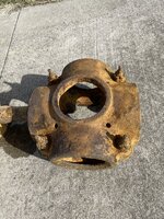
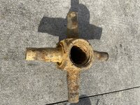
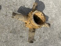
The next four photo's in your post, show a different earlier type of VDM propeller Hub, complete with the VDM extension prop shaft with serrated flange coupling and the prop shaft nut at the front.
This style of VDM Hub was used on earlier aircraft such as Bf 109 E/F1-2, Bf 110 and even some early WW2 He 111 and Ju 88. Again, all these propeller applications were similar but specifically different . Fortunately, I can identify the specific application from the numbers stamped into the Hub casting around the front hole where the big prop nut is fitted into.
In this case the prop shaft and prop nut are fitted. The nut was probably not fully tightened here because the separate pitch-change gearbox assembly has been removed from the rear of the hub. If you are going to undo the big prop nut and prop shaft, this should not be too difficult. I would advise bolting the serrated flange of the propshaft securely to a very strong support of workbench. The propnut has a normal righthand thread and is undone with a long round steel bar. The bar needs to be a close fit in the round holes of the prop nut. I would advise having an extension of about a yard long, in case the nut is actually tight. You might find that a strong heating of the nut will help release it. There should again be a snap ring locating the front bronze cones inside the hub, behind the big nut. These parts are close fit and need good cleaning of the hole to slide out, if it is rusty in there.
If parts are clean it all slides apart, the prop shaft is splined with a master spline but it is a sliding fit in the hub. Of course , dirt and corrosion in there may make it seem a solid fit but, with the snap ring removed and nut off, only dirt or corrosion is holding the the half cones and prop shaft in the hub. Careful cleaning and mechanical technique will get it apart.

Now, just like the other hub, the prop id is stamped around the circular opening for the big nut at the front. Do be careful with the mechanical ways you clean/restore the hub. The stampings are quite well defined in the metal but, where corrosion is present, the numbers may need care to not be lost with excessive mechanical cleaning.

Looking forward to giving you more info as you get some numbers!

Eng

I forgot to add the important point that, the big Prop Nut should have two screws in its outer circumference, about 3/4 of the way down the outside of the nut. One of these screws is longer and enters the propshaft where there are holes to accept it. This locks the Nut. The second screw is short, does not enter the propshaft and acts as a post for a locking wire safety lock to the other screw. These screws must be removed before trying to undo the big prop nut!

Cheers

Eng
 
Sadly my snow blower didn't want to work this last time when I needed it. I've since made some tracks by shovel, but didn't manage to get up there last Saturday due to the snow here. So I'm hoping to get it done next Saturday instead. I kind of expected this might happen, and is the biggest reason I'd moved the 109 off the cart and back into the dig room. To make it easier for me to work on during the bad weather. When I can get out of my own driveway anyways. :p But as soon as I get those cleaned up and some pics, I'll be posting them in here. Those 2 smaller items have me curious as hell at this point. The weather here just wasn't cooperating. I got the new wig today for the link trainer mannequin in the mail today too. So I'll have to try to remember to take a couple of pics of him with the new hairdo too for everyone. The wig it is wearing currently was part of a Dracula costume believe it or not. But it worked as a temporary fix until this new one arrived.

CJ
 
Hi CJ,

Thank You for the update, a pity your work was stopped by snow!
I am looking forward to the results of your work on the prop hubs, I am confident you will get some numbers for me to give you full info of the specific parts.
Cheers

Eng
 
Another Saturday! Has the snow gone? Any updates from the FAAM team about these prop hubs? Stay tuned!

Hope you have a fruitful session!

Eng
 
I'm back to the very first post in this string, where I asked about a 4-blade prop hub, and the internal cross we think goes with it. Nobody knew anything about it, just from the pictures. We said we would clean the items further, hopefully find some markings, and post again. My coworker CJ spent a lot of time doing additional cleaning, but we still could not find any numbers. I took pictures of the further-cleaned parts. The bolts that hold the hub halves together are now much better defined. We have a closer pictures of each side of the cross. We would really like to know what propeller these parts go to, but markings/numbers are elusive. Does this help at all? We don't know what else to do. Thanks.
 

Attachments

  • Unk 4-blade prop hub.JPEG
    Unk 4-blade prop hub.JPEG
    994.1 KB · Views: 6
  • Cross_side 1.JPEG
    Cross_side 1.JPEG
    1.1 MB · Views: 5
  • Cross_side 2.JPEG
    Cross_side 2.JPEG
    1 MB · Views: 5
Hi Larry and welcome back.

May I suggest two things

1 you fully immerse both the barrel halves and the spider in a mix of 9 parts water and 1 part molasses for about 4-6 hours to loosen the rust. Do not leave it longer as the mix will attack any case hardened parts and cause pitting after that. Once removed from the molasses immediately brush with a copper rotary wire brush or stiff nylon brush and spray with a protective coating like WD or it will very quickly rust again. Obviously you will need to wear eye and face protection when rotary brushing.

2 provide some dimensions.

I suspect, from there being only 4 barrel bolts, that this is from a fairly small propeller and that people are subconsciously trying to think of large props because low horsepower 4 blade props are not common.
 
Larry,
I am sorry but, do we have two different hubs here? In these latest pics, one hub with just 4 large barrel bolts and two pics of a different hub spider? Or, did that spider come
out of that barrel?

Cheers

Eng
 
Last edited:
I think you do have two aspects which might give clues. First, if really cleaned up, you have the internal spline, which should yield a good size check and spline count. Also the four large nuts and bolts that hold the barrel together should be possible to id the thread. Possibly USA, Brit or Metric thread?

Cheers

Eng
 
Larry,
I am sorry but, do we have two different hubs here? In these latest pics, one hub with just 4 large barrel bolts and two pics of a different hub spider? Or, did that spider come
out of that barrel?

Cheers

Eng

That is one of the reasons I asked for dimensions. The photos suggest the spider is off a much larger prop but holding the camera further back, or cropping less, would suggest they came from the same unit. A single photo showing both spider and barrel side by side would provide perspective but dimensions would still be needed.
 
Last edited:
The Freeman Army Airfield Museum has a storage room (used to house a coal furnace) that we call the Dig Room. It is where we store WWII aircraft parts that were dug up at Freeman Army Airfield in the late 90's, and some from 2008-2013, that have not yet been cleaned up/identified. Many of the parts you folks have helped to identify came out of that room. With the identification of the hydraulic operating cylinder for a Mk 9 Spitfire a couple of weeks ago, we have become interested in some other propeller parts. We have just begun to clean them up, and they are not yet ready for prime time in terms of finding numbers on them. However, we wonder if just the images of the uncleaned parts would rings any bells in the minds of you folks with a a lot of experience in these matters. Please have a look at the attached pictures, and let us know if you recognize any of these parts. Thanks.
Hi Larry,

After looking around, I think the prop blade root fitting with remains of wooden blade in this first post #1 looks to be a Jablo blade from a Spitfire Mk 9 Rotol 4-Blade hub.
This is not a confirmation, but the metal root fitting looks the same.

Cheers

Eng
 
Last edited:
From what I can see, on the third image there are four grease nipples that based on the Hamilton Standard Counterweight propeller are used to grease the spider arms that the blades rotate on. In the image of the hub rear there are four holes which appear to align with grease nipples, the same as the H/S props. So it is my opinion that the two items may be from the same propeller.
Does the hub come apart/split in half after the bolts are removed?

You know, it could just be, if that strange "Maltese Cross" cut-out is the front face, where the counterweight arms stick out.
Still looking!

Eng
 
Hi Larry,

Here is a photo of a 3-Blade HS Counterweight hub. Yes, I know your hub is 4-Blade, just note the cut-away front face for the counterweights, just like your hub has for 4-blades!
I can't find any pics or info about the 4-Blade hub, possibly yours was a prototype?

Cheers

Eng


hscwhub1_b.jpg
 
Because the barrel halves only have one bolt per side I am suspecting this is for a fairly low powered engine. Why would you need four blades on low power is an interesting question,

Ground clearance? ducted fan? I wonder if we need to be looking at "secret" projects from Germany or Japan.

Obviously it was also designed to mount a spinner so that is another item to include in the search.

Unfortunately, I am just going on the features that I can see. Certainly, the cut-out face of the barrel is similar to the H-S CW 3-bladed hub, as is the general form. The mere 4 bolts at the
barrel join is noticeably a point, but I an thinking that they are quite large bolts.
Agree, the 4-blade bit is strange, and I agree that it could be a foreign adaptation of the H-S CW principle.
Overall, I would expect some vintage H-S expert could join-in!?

Eng
 
I think that is Michael Hope and he was the person who id'd the hub and spider as CW.

I think dimensions are now getting critical as Michael will know from the dimensions on the spider arms what sort of horsepower range the prop will absorb.
 
From what I can see, on the third image there are four grease nipples that based on the Hamilton Standard Counterweight propeller are used to grease the spider arms that the blades rotate on. In the image of the hub rear there are four holes which appear to align with grease nipples, the same as the H/S props. So it is my opinion that the two items may be from the same propeller.
Does the hub come apart/split in half after the bolts are removed?

Hi Michael,

Certainly looking that it is a 4-blade H-S CW type hub. Can you tell us any more about that 4-blade type prop or copies?

Cheers

Eng
 

Users who are viewing this thread

Back