woodstock74
Airman
- 12
- Sep 30, 2020
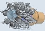
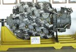
I'm coming up with zeros in my search for this: Who can tell me the degree angle offset between the banks on the R4360 (is there an industry term for this?)? Looking head on towards the engine, Calling bank 1 "zero", what's the angle offset between bank 1 and bank 2? 2 to 3, etc, and is it consistent?
Also...do my eyes deceive me: looking top-down on an individual cylinder, using the leading pushrod as reference, they are obviously rotated to the left relative to airflow or centerline. I've eyeballed it as approximately 7 degrees (this is a wild-ass guess), assuming straight ahead is zero. The question here, as you step through the banks, does this cylinder-angle-relative-to-engine-CL change? I was looking at photos of a display engine and it appeared to me that this angle opens up slightly as you step through the cylinder banks. But it's subtle...maybe 1/2 degree relative difference per bank.
I'm in the process of drawing a 1/48 version, something very simple and not a faithful dimensional reproduction, just MkI eyeball good, to replace what comes with the Special Hobby/Accurate Miniatures kit (which isn't bad at all, it just bugged me that the last cylinder bank wasn't completely modeled). Plus I wanted one for display, so I'll draw up a display stand too. Having both the Special Hobby R4360 as well as the Engines & Things R4360 as reference, I'll then print up my version and then work out the kit integration. Long roads ahead, but fun.