Rivets (1 Viewer)

Ad: This forum contains affiliate links to products on Amazon and eBay. More information in Terms and rules

Modellers of the world!!: say goodbye to all those useless riveting tools!!.

I was focused on Me 410´s and never realised that other german ships don´t exhibit rivets ( Komets!).
Well, a new deployment of knowledge that exceeds the humble view of an enthusiast. Thanks to all for the info.
 
Hi Valengo

The Me410 clearly had lots of Rivets all over the surface of the aircraft. From the images below you can clearly see them:
05-barbette2.JPG.jpeg

17-Exhaust3.JPG.jpeg

27-Canopy3.JPG.jpeg

19-elevator.JPG.jpeg

24-Tailwheel.JPG.jpeg


I am not very familiar with the Me410, but, the panel lines along the fuselage may have received some kind of filling and sanding. I say this because below is an image showing some Me410's under construction with what could be a dark putty substance on the areas where the panel lines are? You may have to check this out further as I do not know for sure.

210a.jpg


Cheers

Clint
 
I am not very familiar with the Me410, but, the panel lines along the fuselage may have received some kind of filling and sanding. I say this because below is an image showing some Me410's under construction with what could be a dark putty substance on the areas where the panel lines are? You may have to check this out further as I do not know for sure.


Cheers

Clint

I believe what you're seeing is sealant placed at lap joints. There also seems to be some type of protective coating applied to the the unpainted surfaces. This is still done today.
 
Last edited:
Hi Valengo

The Me410 clearly had lots of Rivets all over the surface of the aircraft. From the images below you can clearly see them:
Clint

Clinton, thanks for those great pics, but they suport my point of view: is needed such excellent close up to see the rivets. Even in the second pic I can barely see a few ones!. Compare yours with those old pics of WWII and you will understand what I mean.
Cheers.
 
I believe what you're seeing is sealant placed at lap joints. There also seems to be some type of protective coating applied to the the unpainted surfaces. This is still done today.

From what I understand, it was common practice to put a coat of primer along the rivet lines prior to riveting, to protect the freshly-exposed rivet holes, and provide a bit of a barrier between the rivet and skin.

IMO, filling and sanding would have been only used in very special circumstances, due to the labour involved and the weight penalty for a very small aerodynamic gain. You can get a pretty good surface with flush rivets, as seen on the ME410 pics.
 
From what I understand, it was common practice to put a coat of primer along the rivet lines prior to riveting, to protect the freshly-exposed rivet holes, and provide a bit of a barrier between the rivet and skin.
Depends on a few things...

The type and thickness of the material being riveted.

In some cases the material and rivet holes are either already primered or are alodined.

Some applications call for a "wet" installation where the rivet is actually installed with primer being applied before installation.

In some heavier structure, Hi-loks would be used in lieu of rivets and they come already alodined

This will also vary between manufacturers.

IMO, filling and sanding would have been only used in very special circumstances, due to the labour involved and the weight penalty for a very small aerodynamic gain. You can get a pretty good surface with flush rivets, as seen on the ME410 pics.
100% correct. If you could make a surface totally smooth you're only going to pick up a few knots and the effort to maintain that surface isn't practical in a combat environment.
 
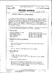
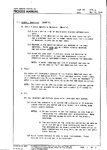
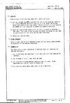
This is from NAA P-51 Mustang factory working specification. In 1979 I have done a similar thing on the LET L-13 all metal glider which had all Al alloy skins fastened with flush rivets either by countersunk and dimpling, using wash primer, car body surfacer and grazing putty. The effect was amazing until we fly the glider after painting. The thin wing of the glider deformed in flight caused several paint clacking along the edges of the skin panels and around the each rivet heads. But most of the flush rivet heads on the fuselage were filled and smoothed almost completely, to a degree we enormously troubled to locate the rivets afterwards when we repaired the glider. The smoothing won't be convenient thing for repairing.
I can assure the procedure in the NAA Spec. below will bring a beautiful and smooth finish on the wings (for your eyes only and if you want an aerodynamically correct surface, that will be another matter ).
 

Attachments

  • u404 01.jpg
    u404 01.jpg
    142.4 KB · Views: 220
  • u404 02.jpg
    u404 02.jpg
    143.2 KB · Views: 219
  • u404 03.jpg
    u404 03.jpg
    103.5 KB · Views: 214
Great info ppposie! About doing this on the L-13. I work with Blanics at the USAFA. We have recently found out that the material they are made out of is similar to 2117T3. Very soft and flexible so it no winder why the putty you applied came off so easily.
 
Last edited:
Blanik!>
That was my biggest (model) painting job ever! I didn't re-start building plastic kits after 25 years from completing this.
I could feel there was no difference in performance between ours and the other unpainted Blaniks at all. In regard of the alloy material of the L-13s I detected some cracks occured on the machined elevator hinge brackets.

Apart from these the LET L-13 is a very nice aircraft to fly. I missed it a lot.
 

Attachments

  • blanikpainted.jpg
    blanikpainted.jpg
    20.8 KB · Views: 260
Last edited:
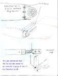
A pile of ADs. It was occured on serial# 026937, in 1978-80 period. On the another ship we even had a breakage of a rod-end fork assembly at the elevator control circuit through an incorrect handling. All of the machined parts on the L-13 series should be closely monitored if you want to fly it and live longer.
 

Attachments

  • L13cracks1978.jpg
    L13cracks1978.jpg
    64 KB · Views: 267
Last edited:
We had them crack on the L-23 "Super Blaniks" which the USAF calls "TG-10B." Also used at the USAFA are the L-13ACs "TG-10C" that have a similar bracket. I'm going to show your infor to my folks tomorrow! Thanks for the info!!!

Here's a link to the newest AD. I have to say that I'm actually the one to report this to the FAA and induced them to write this AD.

FR Doc 2010-7591

THANKS FOR THIS INFORMATION!!!
 
Just looking at the hinge cracks I wonder about two things - both related.

Looks to me that there may be some freedom of movement along the axis of the elevator spar... and either a significant amount of vibration (less likely) or reversible loads along the axis of the spar to 'bend the flange' resulting in the observed cracks..

If there is lateral play perpendicular to the flange support, and particularly if there is a resonant frequency involved - there would be a problem.

Heat treat questions might also come into play if the resulting machined part was higher tensile strength but also more brittle.
 
Last edited:
Just looking at the hinge cracks I wonder about two things - both related.

Looks to me that there may be some freedom of movement along the axis of the elevator spar... and either a significant amount of vibration (less likely) or reversible loads along the axis of the spar to 'bend the flange' resulting in the observed cracks..

If there is lateral play perpendicular to the flange support, and particularly if there is a resonant frequency involved - there would be a problem.

Heat treat questions might also come into play if the resulting machined part was higher tensile strength but also more brittle.

It turns out Bill these were made from bar stock similar to 2117. We had these parts analyzed and they were very porous and contained a lot of impurities. Although the brackets were a little different from each airplane, the manufacturing process was the same..

The whole structure is very 'soft' and when driving normal rivets into the structure, the hole actually elongates while the rivet is swelled during the driving process. When rivets are drilled out almost every hole is already single oversize, just by virtue of the original installation!
 
Vibration; the glider had(s) a tail gear with very simple and hard rubber suspension and we believed it caused since we operated the Blanik from dried soil runways almost always. Some of our club mates were airline mechanics and they said similar things about the alloy materials you reffer to.

BTW do you guys have problems on the riveting on the wing root steel hardware?
 
The reason I mentioned was that after painting whole airframe with a relatively thick layers of paint which became stiff sometime later, and some of the rivet heads on the main spar at the wing root on the upper and the lower surface looked so much loosened, at least to the eye of our inspector. So we had had those fasteners replaced by an aircraft company at its factory nearby. They replaced the existing fasteners, each consisted of an outer sleeve and a rivet core, with modern type fastener system.
 

Users who are viewing this thread

Back