Hi all. First post here.
I thought some might be interested in this. I took a few well know allied fighters to compare their wing sections and found quite a deal of variation. There are nominally 'fast' aircraft with thick sections and 'modern' designs packing older sections.
The aircraft I used were the Spitfire, the P-47, the P-51, the Tempest, the F4U and the Martin Baker MB5.
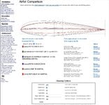
Using Airfoil Tools, I plotted them against each other. When looking at this chart, it is important to remember that all chords are treated in percentages, rather than using dimensions, so that the Leading Edge and Trailing Edge will be at the same point on the chart, despite there being significant dimensional differences.
 airfoiltools.com
if that doesn't work, there is a .pdf attached. If that fails, the old screen cap should suffice.
In any case, it's entirely possible to isolate individual profiles to examine them in detail. Airfoil Tools is pretty interesting, even for people like me who are not engineers.
Interestingly, by far the thickest wing is the F4U. The MB5 was also interesting from the point of view that it used the RAF 34, which had the maximum thickness at 30%, while other modern types, such as the Tempest and P-51, used 38.1 and 38.9 respectively and were consequently better at high speeds than some of the others. The Republic S3 section was interesting for the extreme forward position of its point of maximum camber.
I also found this thread which went into some depth about the relative laminar flow performance on common sections.
Laminar flow at that time was invariably a matter of some compromise. The compromise between high manufacturing tolerances and speed of manufacture during wartime makes it imperfect. IMHO, true laminar flow didn't arrive until after the war. Keeping Reynolds Numbers low wold have been theoretically possible but also compromised by panel fit of gun bay covers, etc..
I thought some might be interested in this. I took a few well know allied fighters to compare their wing sections and found quite a deal of variation. There are nominally 'fast' aircraft with thick sections and 'modern' designs packing older sections.
The aircraft I used were the Spitfire, the P-47, the P-51, the Tempest, the F4U and the Martin Baker MB5.
Using Airfoil Tools, I plotted them against each other. When looking at this chart, it is important to remember that all chords are treated in percentages, rather than using dimensions, so that the Leading Edge and Trailing Edge will be at the same point on the chart, despite there being significant dimensional differences.
Airfoil comparison
Compare the shape and characteristics of airfoils Print out a full size plot for comparison
if that doesn't work, there is a .pdf attached. If that fails, the old screen cap should suffice.
In any case, it's entirely possible to isolate individual profiles to examine them in detail. Airfoil Tools is pretty interesting, even for people like me who are not engineers.
Interestingly, by far the thickest wing is the F4U. The MB5 was also interesting from the point of view that it used the RAF 34, which had the maximum thickness at 30%, while other modern types, such as the Tempest and P-51, used 38.1 and 38.9 respectively and were consequently better at high speeds than some of the others. The Republic S3 section was interesting for the extreme forward position of its point of maximum camber.
I also found this thread which went into some depth about the relative laminar flow performance on common sections.
Laminar flow at that time was invariably a matter of some compromise. The compromise between high manufacturing tolerances and speed of manufacture during wartime makes it imperfect. IMHO, true laminar flow didn't arrive until after the war. Keeping Reynolds Numbers low wold have been theoretically possible but also compromised by panel fit of gun bay covers, etc..
Attachments
Last edited:

