Spitfire MK.XIV and La-7

Ad: This forum contains affiliate links to products on Amazon and eBay. More information in Terms and rules

I know this Soren, but it still does not change the overall effect. Yes the prop has some twist to it, but the difference in overall angle of attack is not enough to equal out the difference in speed.

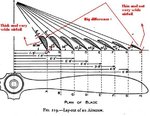
Wrong. Look at the picture below, it illustrates the airflow trough the prop.

Also, the inner part of the prop is of a somewhat laminar flow design, generating little or no airfoil lift - and it is thicker not to provide more lift, but rather for strength.

Look at your image - the inner two cross-sections have no lifting foil to them at all! And the inner 6 inches (assuming a 5' prop) or so is ROUND! 8)

No its not, I just presented a bad sketch then, heres a more illustrative one:
airscrew.jpg


Btw if it was round, then it is quite common knowledge that airflow has no problem getting around a circular surface=Air pressure equal to "Free Airstream", but no thrust.

Also, if you're going to post a link, post one that goes somewhere meaningful, not just to the image you've arleady presented :)

I never posted that pic ! :confused:

As for planes flying in 1803... no engines means no self powered planes - period.

Ever heard about the "bicycle", runs on the "Human" engine ;)
 

Attachments

  • prop1_139.gif
    prop1_139.gif
    16.8 KB · Views: 1,452
Soren said:
I know this Soren, but it still does not change the overall effect. Yes the prop has some twist to it, but the difference in overall angle of attack is not enough to equal out the difference in speed.

Wrong. Look at the picture below; it illustrates the airflow trought the prop.

Also, the inner part of the prop is of a somewhat laminar flow design, generating little or no airfoil lift - and it is thicker not to provide more lift, but rather for strength.

Look at your image - the inner two cross-sections have no lifting foil to them at all! And the inner 6 inches (assuming a 5' prop) or so is ROUND! 8)

No its not, I just presented a bad sketch then, heres a more illustrative one:
airscrew.jpg

This is a low-speed prop, like you might find on a cessna. Hardly relevant to this discussion.

Why don't you figure out the thrust difference for the angle of twist involved (and prop area, which is smaller for the inner part of the blade), and you will see that at high speed this part of the prop is not producing positive thrust.

Soren said:
Btw if it was round, then we both know that air has no problem getting around a circular surface.

Say what? A round surface is an airfoil just like any other. It is really just a laminar airfoil with super extreme thickness. Of course the air has a hard time getting around it.

Soren said:
Also, if you're going to post a link, post one that goes somewhere meaningful, not just to the image you've arleady presented :)

I never posted that pic ! :confused:

You changed the link, when I replied, it went to the .jpg you'd already posted. No problem, I've done that kind of thing myself.

Soren said:
As for planes flying in 1803... no engines means no self powered planes - period.

Ever heard about the "bicycle", runs on the "Human" engine ;)

LOL - no plane built in the 1900's or earlier was going to run off of human power. It took spaceage materials and an extreme athelete to do it in the late 80's or early 90's.

=S=

Lunatic
 
This is a low-speed prop, like you might find on a cessna. Hardly relevant to this discussion.

Still the same shape ! This one just hasnt got the ability of controllable pitching, but the propeller airfoil is still the same shape.

Why don't you figure out the thrust difference for the angle of twist involved (and prop area, which is smaller for the inner part of the blade), and you will see that at high speed this part of the prop is not producing positive thrust.

What do you think prop-pitching is for ???

Say what? A round surface is an airfoil just like any other. It is really just a laminar airfoil with super extreme thickness. Of course the air has a hard time getting around it.

You don't get it...

LOL - no plane built in the 1900's or earlier was going to run off of human power. It took spaceage materials and an extreme athelete to do it in the late 80's or early 90's.

It didnt take space age equipment to help it fly, how then to you think a simple glider flies(By added speed to the wings offcourse, wich can be achieved by running !) Anyway my point was that the opportunity was there !
 
It didnt take space age equipment to help it fly, how then to you think a simple glider flies(By added speed to the wings offcourse, wich can be achieved by running !)

running will aid take off however by gliding you're not using human power to stay airborn...........
 
Soren said:
This is a low-speed prop, like you might find on a cessna. Hardly relevant to this discussion.

Still the same shape !

No they are not. The inner part of the prop design is different for high speed props. For low speed props, they maintain the shape further down because strength is not such an issue and production is easier.

Soren said:
Why don't you figure out the thrust difference for the angle of twist involved (and prop area, which is smaller for the inner part of the blade), and you will see that at high speed this part of the prop is not producing positive thrust.

What do you think prop-pitching is for ???

But at high speeds even at maximum pitch the inside of the prop cannot produce as much thust as the outside, even given the twist involved in the overall prop.

Soren said:
Say what? A round surface is an airfoil just like any other. It is really just a laminar airfoil with super extreme thickness. Of course the air has a hard time getting around it.

You don't get it...

Sure I do. You are claiming a round surface has no drag? Clearly bullet design proves this is WRONG.

Soren said:
LOL - no plane built in the 1900's or earlier was going to run off of human power. It took spaceage materials and an extreme athelete to do it in the late 80's or early 90's.

It didnt take space age equipment to help it fly, how then to you think a simple glider flies(By added speed to the wings offcourse, wich can be achieved by running !) Anyway my point was that the opportunity was there !

And simple gliders were flying back in the 1800's. Success was limited because the science of lift was lacking, and materials did not allow a light enough frame of sufficient strength for "hang" type gliders.

=S=

Lunatic
 
No they are not. The inner part of the prop design is different for high speed props. For low speed props, they maintain the shape further down because strength is not such an issue and production is easier.

Yes they are ! And a low speed prop also runs at the same max revolution-rate of about 3000rpm, so why should it be any less strong ?? (The centrifugal forces are the same !)

Proof at the bottom of the page...

But at high speeds even at maximum pitch the inside of the prop cannot produce as much thust as the outside, even given the twist involved in the overall prop.

Proof please !

(About the circular surface; Im getting you a link.)

And simple gliders were flying back in the 1800's. Success was limited because the science of lift was lacking, and materials did not allow a light enough frame of sufficient strength for "hang" type gliders.

I guess you don't know that it has been proved not so long ago, that even Leonardo da vinci's designs from the 17th century would have flown. (Yes it was tried in practice aswell, and it worked)


Anyway, look at this P-51's prop below:
 

Attachments

  • p51prop-c_195.jpg
    p51prop-c_195.jpg
    85.1 KB · Views: 1,341
Soren said:
No they are not. The inner part of the prop design is different for high speed props. For low speed props, they maintain the shape further down because strength is not such an issue and production is easier.

Yes they are ! And a low speed prop also runs at the same max revolution-rate of about 3000rpm, so why should it be any less strong ?? (The centrifugal forces are the same !)

No, the props on typical private aircraft do not turn at anywhere near the typical ~1250-1500 rpm maximum of a fighter.

Soren said:
Proof at the bottom of the page...

Umm, what is that supposed to prove. That's an H&S standard prop and does not have the same inner profile as used on radials like the LA7.

The prop becomes increasingly efficient the futher toward the tip, as long as it does not exceed mach, because it traveling faster and therefore further per rotation. Because of this, the pitch at maximum thrust is optimimized for the outer part of the blade, not the inner part of the blade, which is given more pitch to try to compensate. Because WE KNOW the outer part of the blade produces the most thrust, and because we know that at some speed the plane will ride the prop, we know that at some speed prior to this the inner part of the prop must stop generating postive thrust before the outer part.

The NACA document I already gave you shows that pressure for cooling is reduced by 25% compared to free-stream airflow, because of the prop.

The best helix angle is as if the blade was a wing producing much more lift than drag, roughly 45° in practice. However due to the shape of the propeller only part of the blade can actually be operating at peak efficiency, the outer part of the blade produces the most thrust and so the blade is positioned at a pitch that gives optimum angle to that portion. Since a large portion of the blade is therefore at an inefficient angle the inboard ends of the blade are subsumed into a streamlined spinner to reduce the resistance torque that would otherwise be created.
http://encyclopedia.lockergnome.com/s/b/Propeller#Aircraft_propellers

Now if the inner part of the prop is at an inefficent angle, they cannot produce as much thrust as the outer part. Right?

Or are you trying to say that the inner part of the prop produces as much thrust as the outer part?

=S=

Lunatic
 
*sigh*

Well atleast we moved from "the air is already slowed down 20% by passing through the prop." to "the air is already slowed down 20% by going through the inner part of the prop at high speed" Now we just need to leap over to the coclusion that the air really isnt slowed down at all.


No, the props on typical private aircraft do not turn at anywhere near the typical ~1250-1500 rpm maximum of a fighter.

RG a single-piston-engined Cessna 210, has a Prop RPM of 2700 ;) Most single-piston-engined Cessna's run at over 2500 in prop RPM.

Umm, what is that supposed to prove. That's an H&S standard prop and does not have the same inner profile as used on radials like the LA7.

What do you think its supposed to prove ?! You said "High speed props" doesnt have airfoil-profile all the way down, but they DO, and I proved it to you !

The prop becomes increasingly efficient the futher toward the tip, as long as it does not exceed mach, because it traveling faster and therefore further per rotation. Because of this, the pitch at maximum thrust is optimimized for the outer part of the blade, not the inner part of the blade, which is given more pitch to try to compensate. Because WE KNOW the outer part of the blade produces the most thrust, and because we know that at some speed the plane will ride the prop, we know that at some speed prior to this the inner part of the prop must stop generating postive thrust before the outer part.

*Sigh*

Didnt you read ANYTHING at the NASA site ??!

The NACA document I already gave you shows that pressure for cooling is reduced by 25% compared to free-stream airflow, because of the prop.

Listen here.. NACA documents are good for flight specification and aircraft specifications, but they are too bloody old for beeing of any real use when talking advanced aerodynamics ! (We have come a far way since those documents !)

Sure the base of the prop moves slower than the tip of the prop, but thats why the prop is twisted, and has a thicker airfoil shape at the base. As the speed increases the thrust decreases, but not from the base of the prop out to the tip, it gradually decreases on the whole span of the prop. At high speeds the fighters of WW2 had the opportunity of prop-pitching, wich greatly improved the the thrust of the propeller at high speed.

The most thrust is offcourse at the tip of the prop, but it isnt much. The whole point is that even at high speed, the inner part of the prop still sets up a pressure lower than free stream in front of it, and higher than free stream behind it.


The best helix angle is as if the blade was a wing producing much more lift than drag, roughly 45° in practice. However due to the shape of the propeller only part of the blade can actually be operating at peak efficiency, the outer part of the blade produces the most thrust and so the blade is positioned at a pitch that gives optimum angle to that portion. Since a large portion of the blade is therefore at an inefficient angle the inboard ends of the blade are subsumed into a streamlined spinner to reduce the resistance torque that would otherwise be created.
http://encyclopedia.lockergnome.com/s/b/Propeller#Aircraft_propellers

Now if the inner part of the prop is at an inefficent angle, they cannot produce as much thrust as the outer part. Right?

Or are you trying to say that the inner part of the prop produces as much thrust as the outer part?

From the NASA site:

The blades are usually long and thin, and a cut through the blade perpendicular to the long dimension will give an airfoil shape. Because the blades rotate, the tip moves faster than the hub. So to make the propeller efficient, the blades are usually twisted. The angle of attack of the airfoils at the tip is lower than at the hub because it is moving at a higher velocity than the hub.

And incase you missed it the last time, here's a picture of the airflow behind a working propeller, from base to tip:
 

Attachments

  • prop1_186.gif
    prop1_186.gif
    16.8 KB · Views: 1,340
Soren said:
*sigh*

Well atleast we moved from "the air is already slowed down 20% by passing through the prop." to "the air is already slowed down 20% by going through the inner part of the prop at high speed" Now we just need to leap over to the coclusion that the air really isnt slowed down at all.


No, the props on typical private aircraft do not turn at anywhere near the typical ~1250-1500 rpm maximum of a fighter.

RG a single-piston-engined Cessna 210, has a Prop RPM of 2700 ;) Most single-piston-engined Cessna's run at over 2500 in prop RPM.

Okay, I'll take your word for it. But the props are no where near as large as WWII aircraft, which had to limit prop RPM to about 1600 rpm. Smaller props mean less stress, less torque, less vibration, and higher allowable tip speeds.

Soren said:
Umm, what is that supposed to prove. That's an H&S standard prop and does not have the same inner profile as used on radials like the LA7.

What do you think its supposed to prove ?! You said "High speed props" doesnt have airfoil-profile all the way down, but they DO, and I proved it to you !

No, the P-51 is an inline, and it uses the US HS prop. Look at the soviet props, the german props, and even many british props, they all have a smaller thicker shaft area near the base. US prop design was years ahead of the rest. And even on US radials, you see the same thing, or you see cuffs on the inner part of the prop to try to improve cooling.

But it really does not matter. Even with the airfoil, the lower speed and less than optimal angle of attack mean the inner portion of the prop will become inefficient when the outer portion of the prop is delivering peak thrust at high airspeed.

Soren said:
Didnt you read ANYTHING at the NASA site ??!

Yes I read the whole thing. What there supports your position?

Soren said:
The NACA document I already gave you shows that pressure for cooling is reduced by 25% compared to free-stream airflow, because of the prop.

Listen here.. NACA documents are good for flight specification and aircraft specifications, but they are too bloody old for beeing of any real use when talking advanced aerodynamics ! (We have come a far way since those documents !)

We are talking about WWII designs. The NACA tests were valid then, and they are still valid now, unless proven mistaken, which in this case has not happened.

Soren said:
Sure the base of the prop moves slower than the tip of the prop, but thats why the prop is twisted, and has a thicker airfoil shape at the base. As the speed increases the thrust decreases, but not from the base of the prop out to the tip, it gradually decreases on the whole span of the prop. At high speeds the fighters of WW2 had the opportunity of prop-pitching, wich greatly improved the the thrust of the propeller at high speed.

No, it has a thicker airfoil shape at the bottom mostly for strength. Peak thrust peformance is obtatined at about 45 degrees static, at speed, this rises to about 65 degrees. Minimum drag performance is achieved at angles greater than 45 degrees/65 degrees at speed. The typical WWII prop allows a max coarse pitch of about 65 degrees at 75% of the prop span, corresponding to about 80-85 degrees near the hub. Because the inner part cannot rotate fast enough to generate postive thrust, the concern becomes minimizing drag.

Soren said:
The most thrust is offcourse at the tip of the prop, but it isnt much. The whole point is that even at high speed, the inner part of the prop still sets up a pressure lower than free stream in front of it, and higher than free stream behind it.

But the NACA documents and other sources I've given you clearly show that pressure at the cowl is below free-stream!

If the inner part of the prop were able to still make positive thrust, it means the outer part of the prop could make more thrust than it is and propell the plane faster. As long as increasing the pitch of the outer part of the prop will create more thrust than is lost at the inner part then it makes sense to do so.

You are saying that a mere 25 degree (maximum) increase in pitch and a doubling of chord is making up for more than 3x difference in speed. That's absurd. If this were the case, shorter thicker props with higher angles of attack would have been used.

Soren said:
The best helix angle is as if the blade was a wing producing much more lift than drag, roughly 45° in practice. However due to the shape of the propeller only part of the blade can actually be operating at peak efficiency, the outer part of the blade produces the most thrust and so the blade is positioned at a pitch that gives optimum angle to that portion. Since a large portion of the blade is therefore at an inefficient angle the inboard ends of the blade are subsumed into a streamlined spinner to reduce the resistance torque that would otherwise be created.
http://encyclopedia.lockergnome.com/s/b/Propeller#Aircraft_propellers

Now if the inner part of the prop is at an inefficent angle, they cannot produce as much thrust as the outer part. Right?

Or are you trying to say that the inner part of the prop produces as much thrust as the outer part?

From the NASA site:

The blades are usually long and thin, and a cut through the blade perpendicular to the long dimension will give an airfoil shape. Because the blades rotate, the tip moves faster than the hub. So to make the propeller efficient, the blades are usually twisted. The angle of attack of the airfoils at the tip is lower than at the hub because it is moving at a higher velocity than the hub.

Making the prop "efficient" does not mean that it produces postive thrust along its whole span. This paragraph does not say what you imply it does.

=S=

Lunatic

PS: All this is mute - time and again in your ref'd sources they point out that during WWII it was proven that radial designs did not have inherantly more drag than inline designs. And that was the point you made that started this whole digression.
 
No, the P-51 is an inline, and it uses the US HS prop. Look at the soviet props, the german props, and even many british props, they all have a smaller thicker shaft area near the base.

Look at the bottom at the page, and you will see that you are very wrong.

US prop design was years ahead of the rest.

Im seeing strong signs of Bias, cause thats just silly !

But it really does not matter. Even with the airfoil, the lower speed and less than optimal angle of attack mean the inner portion of the prop will become inefficient when the outer portion of the prop is delivering peak thrust at high airspeed.

The tip of the propeller hardly creates more thrust than the lower part of the propeller, as its AoA is different.

Also we have yet to see any info on what prop design NACA's "Theory" is based on ! (Remember some props arent twisted !)

What there supports your position?

Every last bit of it !

We are talking about WWII designs. The NACA tests were valid then, and they are still valid now, unless proven mistaken, which in this case has not happened.

Well they HAVE been proven mistaken ! And as i said before, we don't even know what the propeller-design used in these tests were, it could just as well have been an untwisted prop as not.

No, it has a thicker airfoil shape at the bottom mostly for strength.

*Sigh* No no no no...

But the NACA documents and other sources I've given you clearly show that pressure at the cowl is below free-stream!

Propeller design ?

If the inner part of the prop were able to still make positive thrust, it means the outer part of the prop could make more thrust than it is and propell the plane faster. As long as increasing the pitch of the outer part of the prop will create more thrust than is lost at the inner part then it makes sense to do so.

Ever heard of DRAG ? There is a certain point where the prop can't propell the plane forward because it has to deal with drag, and if the thrust isnt sufficient to counter this drag, then the plane won't move.

You are saying that a mere 25 degree (maximum) increase in pitch and a doubling of chord is making up for more than 3x difference in speed. That's absurd. If this were the case, shorter thicker props with higher angles of attack would have been used.

And as you've seen the inner part of the prop is a thick short airfoil.


PS: All this is mute - time and again in your ref'd sources they point out that during WWII it was proven that radial designs did not have inherantly more drag than inline designs. And that was the point you made that started this whole digression.

Show where that is stated :!:

You've got ot understand that the prop blades are shaped like a wing, and therefore, eventhough the inner part isnt spinning as fast, it still creates a low air-pressure infront of it and high air pressure behind it. It works just like a wing does, this is just in the vertical plane instead. And as I've proven to you the prop airfoil IS thicker at the base, thus creating more lift pr revolution.
 

Attachments

  • detail_spitfire_ix_07_146.jpg
    detail_spitfire_ix_07_146.jpg
    26.5 KB · Views: 1,229
  • detail_spitfire_ix_05_183.jpg
    detail_spitfire_ix_05_183.jpg
    32.1 KB · Views: 1,238
i feel this conversation will long be remembered on the site asone of the all time greats, well done and kepp it up..........

great pics as well...........
 
Soren said:
No, the P-51 is an inline, and it uses the US HS prop. Look at the soviet props, the german props, and even many british props, they all have a smaller thicker shaft area near the base.

Look at the bottom at the page, and you will see that you are very wrong.

LOL - you use a late model Spitfire as your example, one which has benefited from access to the NACA PRT research. Let's look at some relevant examples:

detail_spitfire1_02.jpg


Spitfire%205+2%20(2).jpg


ta152_2.jpg


FW190-1s.jpg


FW190-F2Trop-14s.jpg


9-7-2002-9-25-yak-3_airfield.jpg


Soren said:
US prop design was years ahead of the rest.

Im seeing strong signs of Bias, cause thats just silly !

No, it is a fact. The Germans (and the Soviets and even the Brits until very late in the war) all made several errors in prop design. The most significant was tapering of the trailing edge to an eliptical form, which robs thrust with no real benefit. Only the USA had the necessary research wind tunnels to truely optimize the props as was done in the NACA PRT research, which yeilded what are still the basis of optimized high-speed props today.

I'll reply to the rest of your argument soon. The math is interesting, but being the weekend I have miminal time for it and the associated graphics are quite an effort for me (learning a new paint program).

=S=

Lunatic
 
Pic 2 and 6 clearly shows airfoil shape all the way down. And the Fw-190 has smaller fans behind the Prop, to create the extra pressure needed.

LOL - you use a late model Spitfire as your example, one which has benefited from access to the NACA PRT research. Let's look at some relevant examples:

And why do you think I am ? your showing pictures of "Old" fighters, while were talking the late-war Spit XIV and LA-7 here ! ;)

Have you ever seen a prop blade from a Spit XIV ? Airfoil all the way !!

Only the USA had the necessary research wind tunnels

Thats a lie ! Germany made lots of wind-tunnel tests throughout the war, and if you'd read about Project-X then you would know this !

Germany werent lacking behind at all, if your using the Fw-190's prop as an example, then you should note the fans behind it !

Btw Britain had Wind-tunnel's aswell, and the Spit already had a fully airfoil shaped prop in late 41. (Pic below)

SpitV_BM597.jpg


The prop-airfoil is thicker at the base and pitched at a lower AoA, thus creating more lift, while the tip of the prop-airfoil is thin and pitched at a higher AoA, thus creating less lift.


but being the weekend I have miminal time for it and the associated graphics are quite an effort for me (learning a new paint program).

Don't use your own graphics RG, we need real aerodynamic research graphics from reliable sources, or else were gonna get nowhere.
 
Soren,

Here are the problems with your "equal thrust through higher AOA and airfoil thickness" argument.

----------------------------------------------------

Let's consider two points on a prop, one at 5 feet and one at 2 feet from center, rotating at 1000 rpm. Therefore, as shown earlier, the rotational speed of the prop at the 5 foot mark is 355 mph, and at the 2 foot mark is 142 mph. Lets assume the maximum speed of the aircraft is about 355 mph and the pitch of the prop at 5' is 45 degrees.

Therefore, after accounting for the forward speed of the plane the airspeed across the prop airfoil at 5 feet is 505 mph, and at 2 feet it is 382 mph. So the air flows across the prop airfoil at 5 feet 31.4% faster than it does at 2 feet. In order for the airfoil at 2 feet to generate as much lift as the airfoil at 5 feet its upper surface will have to be 31.4% longer, as depicted below:

airfoil_chord_difference_1_vs_1.3_01_875.jpg


Clearly this is an absurd difference in chord, the 2 foot chord being impractically steep and producing far more drag than it would lift!

But there is another problem still...

Let's ignore the impracticallity of the chord thickness needed, and assume the 2 foot airfoil can generate as much lift at 382 mph as the 5 foot airfoil can at 505 mph. Lets further assume the drag at these relative speeds is equal (which they would not be).

Airfoils generate lift perpendicular to the airflow through which they pass, and drag in the same direction as the airflow. Using vectors I've depicted this in the diagram below, the 5' section shown on the left:

prop_thrust_vectors_06_118.jpg

As is clearly shown, even making the above assumptions, the 2' airfoil point does not generate nearly the thrust made at the 5' airfoil point. And if you think the angle I've depicted for the 2' section is contrived to make it look bad, quite the reverse is true. While the 5' point angle is (obviously) 45 degrees, at the 2 foot point it would be over 79 degrees, which is steeper than that depicted.

The fact is the inner part of the prop cannot generate as much lift as the outer part, and no chord thickness is going to overcome this. At high speeds, the AOA is going to become extreme at the inner part of the prop, and very little of what lift is generated is going to result in usable thrust. Pressure will build in front of it (and thus diverge to the outside), and pressure behind the inner part of the prop will be less than the free stream airflow.

=S=

Lunatic
 
Soren said:
Pic 2 and 6 clearly shows airfoil shape all the way down. And the Fw-190 has smaller fans behind the Prop, to create the extra pressure needed.

You must be blind. The only "airfoil" shape at the root of these props is leftover from that above. What do you expect them to have done - made them square? Abruptly made them round? LOL

Soren said:
LOL - you use a late model Spitfire as your example, one which has benefited from access to the NACA PRT research. Let's look at some relevant examples:

And why do you think I am ? your showing pictures of "Old" fighters, while were talking the late-war Spit XIV and LA-7 here ! ;)

Well, we got a bit off topic to prop efficiency issues. But the point, except for the British and the USA, the airfoil characteristics near the root are relatively mimimal. But that does not really matter, as I've shown in my previous post, their is still a loss of pressure behind the inside of the prop rotation at high speed.

Soren said:
Have you ever seen a prop blade from a Spit XIV ? Airfoil all the way !!

Sure, but that's because they were privy to the NACA PRT research.

Soren said:
Only the USA had the necessary research wind tunnels

Thats a lie ! Germany made lots of wind-tunnel tests throughout the war, and if you'd read about Project-X then you would know this !

You have not researched windtunnles much. If you do you will see that the NACA wind tunnels were far superior to those in the rest of the world. No one else had the 500 mph closed loop or +20 atmousphere windtunnels to do the this kind of research.

Soren said:
Germany werent lacking behind at all, if your using the Fw-190's prop as an example, then you should note the fans behind it !

Sure, because they had to deal with the lack of cooling caused by the low pressure area immeadiately behind the prop.

Soren said:
Btw Britain had Wind-tunnel's aswell, and the Spit already had a fully airfoil shaped prop in late 41. (Pic below)

They got full access to the NACA PRT research as it was happening in the very late 30's and early 40's. The Brit wind tunnels were insufficient for such research. They simply lacked millions of $ to spend on wind tunnels.

Soren said:
The prop-airfoil is thicker at the base and pitched at a lower AoA, thus creating more lift, while the tip of the prop-airfoil is thin and pitched at a higher AoA, thus creating less lift.

That's pure poop.

Soren said:
but being the weekend I have miminal time for it and the associated graphics are quite an effort for me (learning a new paint program).

Don't use your own graphics RG, we need real aerodynamic research graphics from reliable sources, or else were gonna get nowhere.

My graphics simply superimpose multiple graphics from such sources to more clearly illistrate the point. If you like, I can reference the original sources.

=S=

Lunatic
 
You must be blind. The only "airfoil" shape at the root of these props is leftover from that above. What do you expect them to have done - made them square? Abruptly made them round? LOL

What are you talking about here ?

Well, we got a bit off topic to prop efficiency issues. But the point, except for the British and the USA, the airfoil characteristics near the root are relatively mimimal. But that does not really matter, as I've shown in my previous post, their is still a loss of pressure behind the inside of the prop rotation at high speed.

Kind of funny how you changed it from "20% loss of airflow through the propeller" to "20 % loss of airflow through the inner propeller at high speeds", whats next ?

Anyway Im gonna need reliable sources who specifically says that twisted pitchable props are not creating thrust near the hub at high speed.

You have not researched windtunnles much. If you do you will see that the NACA wind tunnels were far superior to those in the rest of the world. No one else had the 500 mph closed loop or +20 atmousphere windtunnels to do the this kind of research.

Im going to need a very specific Source on that !! As in the department of aerodynamics, the Germans were ahead of the Allies !

Sure, because they had to deal with the lack of cooling caused by the low pressure area immeadiately behind the prop.

And as you have seen(If you've ever been up close), they are all airfoil shaped thus creating the extra pressure.

They got full access to the NACA PRT research as it was happening in the very late 30's and early 40's. The Brit wind tunnels were insufficient for such research. They simply lacked millions of $ to spend on wind tunnels.

But thats not what you said ealier, no no.. "Only the U.S. had those kind of props" and "The Germans (and the Soviets and even the Brits until very late in the war ) all made several errors in prop design." ! ;)

That's pure poop.

:D Your going to regret saying that !

Fact is, that a thinner airfoil that is at a high AoA will generate less lift than a thicker airfoil at a lower AoA. If your going to deny this aswell, then you really have no clue what your talking about !

My graphics simply superimpose multiple graphics from such sources to more clearly illistrate the point. If you like, I can reference the original sources.

Sure, lets hear them.
 
Soren said:
You must be blind. The only "airfoil" shape at the root of these props is leftover from that above. What do you expect them to have done - made them square? Abruptly made them round? LOL

What are you talking about here ?

Your claim that the airfoil of the prop is extended to the root on the photo's I provided.

Soren said:
Well, we got a bit off topic to prop efficiency issues. But the point, except for the British and the USA, the airfoil characteristics near the root are relatively mimimal. But that does not really matter, as I've shown in my previous post, their is still a loss of pressure behind the inside of the prop rotation at high speed.

Kind of funny how you changed it from "20% loss of airflow through the propeller" to "20 % loss of airflow through the inner propeller at high speeds", whats next ?

When I said 20% loss through the prop, the context was clearly concerning the fuselage/nose section, not the whole of the prop. That'd be stupid - if the airflow behind the prop were 20% lower than the free-stream airflow across the whole prop, the plane would go backwards! We were talking about the nose of the plane and we were talking about high speeds.

Please don't try to put my statements in this conversation out of context.
Anyway Im gonna need reliable sources who specifically says that twisted pitchable props are not creating thrust near the hub at high speed.

Soren said:
Anyway Im gonna need reliable sources who specifically says that twisted pitchable props are not creating thrust near the hub at high speed.

Where is your "reliable source" who specifically says they are?

Soren said:
You have not researched windtunnles much. If you do you will see that the NACA wind tunnels were far superior to those in the rest of the world. No one else had the 500 mph closed loop or +20 atmousphere windtunnels to do the this kind of research.

Im going to need a very specific Source on that !! As in the department of aerodynamics, the Germans were ahead of the Allies !

Ummm.. In about 1936 this was true. Then the US government allocated about $10 million for wind-tunnel construction and research projects, specifically in reaction to the German wind tunnel built I believe in 1935. You can find the sources for this easily - just research windtunnels, I suggest you start here:

http://www.hq.nasa.gov/office/pao/History/SP-440/contents.htm

And notice the following quote:

[27] The resulting 8-foot high speed tunnel was unique, something no other country possessed. Since World War II was right around the corner, the tunnel had strategic value. The first tests, in fact, evaluated the effects of machine gun and cannon fire on the lift and drag properties of wing panels. This led logically to checking the effects of rivet heads, lapped joints, slots, and other irregularities on drag. Such tests demonstrated drag penalties as high as 40 percent over aerodynamically smooth wings. Aircraft manufacturers quickly switched to flush rivets and joints.
http://www.hq.nasa.gov/office/pao/History/SP-440/ch3-5.htm

Soren said:
Sure, because they had to deal with the lack of cooling caused by the low pressure area immeadiately behind the prop.

And as you have seen(If you've ever been up close), they are all airfoil shaped thus creating the extra pressure.

As I've shown you, they don't. The inner part of the prop produces positive thrust at low airspeeds and (relatively) low angles of attack. This is good for climb. At high airspeeds, the inner part of the prop is just a necessary evil, and is turned sharply into the airstream to minimize drag and negative torque effects.

Soren said:
They got full access to the NACA PRT research as it was happening in the very late 30's and early 40's. The Brit wind tunnels were insufficient for such research. They simply lacked millions of $ to spend on wind tunnels.

But thats not what you said ealier, no no.. "Only the U.S. had those kind of props" and "The Germans (and the Soviets and even the Brits until very late in the war ) all made several errors in prop design." ! ;)

Even though the Brit's had access to the NACA wind tunnel data from the PRT, they still persisted in making the trailing edge of the prop somewhat eliptical in shape until very late in the war. This robs thrust for no appreciable benefit. No conflict here.

Soren said:
That's pure poop.

:D Your going to regret saying that !

Fact is, that a thinner airfoil that is at a high AoA will generate less lift than a thicker airfoil at a lower AoA. If your going to deny this aswell, then you really have no clue what your talking about !

To a degree yes, but you cannot push that to extremes, if you could, every wing would be hemispherical in shape. A thicker airfoil also creates more drag, and (in extreme cases) will encounter mach effects at a very low speed.

The pressure differential of an airfoil is calculated as the difference in air pressure above and below the wing. The air above the airfoil is at a lower pressure because it must travel further to reach the back of the airfoil than the airflow below the airfoil. As I have clearly shown, the required increase in thickness for the inner part of the prop airfoil to achieve the same "lift" as outer part is beyond reasonability. Look at the image I gave you!

My graphics simply superimpose multiple graphics from such sources to more clearly illistrate the point. If you like, I can reference the original sources.

Sure, lets hear them.[/quote]

http://www.auf.asn.au/groundschool/propeller.html
http://www.geocities.com/donshoebridge/h-stab.html
http://www.hq.nasa.gov/office/pao/History/SP-445/ch4-1.htm
http://encyclopedia.lockergnome.com/s/b/Propeller#Aircraft_propellers
http://mesun4.wustl.edu/ccm/galscifi.html
http://www.grc.nasa.gov/WWW/K-12/airplane/propeller.html
http://www.allstar.fiu.edu/aero/Propulsion1.htm
http://home.att.net/~historyzone/Fisher.html

=S=

Lunatic
 
When I said 20% loss through the prop, the context was clearly concerning the fuselage/nose section, not the whole of the prop.

On the La-7 the fuselage covers alot of prop area RG !

That'd be stupid - if the airflow behind the prop were 20% lower than the free-stream airflow across the whole prop, the plane would go backwards!

Thats right !

We were talking about the nose of the plane and we were talking about high speeds.

We were NOT talking high speed ! And there is ansolutely NOTHING that implies we did.

Where is your "reliable source" who specifically says they are?

You see im not the one who needs one, cause im not the one making claims ! ;)

Anyhow I've provided many sites with pictures that illustrated the airflow through the intire prop-span. (And you just linked one of mine ! ;) )


Ummm.. In about 1936 this was true. Then the US government allocated about $10 million for wind-tunnel construction and research projects, specifically in reaction to the German wind tunnel built I believe in 1935. You can find the sources for this easily - just research windtunnels, I suggest you start here:

But you were suggesting that the Germans, British, and the Russains didnt build a Windtunnel research center ! And that fully airfoiled props werent used on German a/c's, wich is downright untrue ! (Proof below)
63_Me109G_Luftwaffe_4_4.jpg


Also did the U.S. ever have jets in WW2 ? NO ! Or did they have something like this: (NO)
http://www3.sympatico.ca/slavek.krepelka/gismos/fooger1.jpg

Face it, we were lacking compared to the Germans in that department !

As I've shown you, they don't. The inner part of the prop produces positive thrust at low airspeeds and (relatively) low angles of attack. This is good for climb. At high airspeeds, the inner part of the prop is just a necessary evil, and is turned sharply into the airstream to minimize drag and negative torque effects.

Untrue, at high speed the inner part of the prop still creates higher than free-stream airflow behind it.

Even though the Brit's had access to the NACA wind tunnel data from the PRT, they still persisted in making the trailing edge of the prop somewhat eliptical in shape until very late in the war. This robs thrust for no appreciable benefit. No conflict here.

And an example would be good, show us a late war UK fighter with these inferior props.

To a degree yes, but you cannot push that to extremes, if you could, every wing would be hemispherical in shape. A thicker airfoil also creates more drag, and (in extreme cases) will encounter mach effects at a very low speed.

Your example has nothing to do with what im talking about, your "Graphically Displayed" airfoil was only "thicker" than the thinner airfoil, but not wider !

You've got to understand the the tip of the prop isnt very wide, and that the base is both wider and thicker, thus creating much more lift than the thinner and shorter tip.

The pressure differential of an airfoil is calculated as the difference in air pressure above and below the wing. The air above the airfoil is at a lower pressure because it must travel further to reach the back of the airfoil than the airflow below the airfoil. As I have clearly shown, the required increase in thickness for the inner part of the prop airfoil to achieve the same "lift" as outer part is beyond reasonability. Look at the image I gave you!

As I explained above your imaged is totally unrealistic, and the thicker airfoil shape you presented wasnt even wider than the tip airfoil next to it !!

At the bottom of the page is an accurate depiction of the difference between the tip of the prop airfoil, and the base of the prop airfoil.


RG I provided the NASA site, and it doesnt agree even ONE bit with your claim ! And neither does any other source up there worth mentioning.

The German experiment only showed that when moving the Radiator up close to the prop, the airflow was too "Turbulent" to be any effective for "Cooling", but the airflow was still higher than free stream behind the prop.
 

Attachments

  • airscrew2_345.jpg
    airscrew2_345.jpg
    53.3 KB · Views: 1,753
Soren said:
When I said 20% loss through the prop, the context was clearly concerning the fuselage/nose section, not the whole of the prop.

On the La-7 the fuselage covers alot of prop area RG !

Compared to other radial designs, the La7 has one of the slimest nose/cowl contours of any WWII plane.

Soren said:
We were talking about the nose of the plane and we were talking about high speeds.

We were NOT talking high speed ! And there is ansolutely NOTHING that implies we did.

Of course we were. We were talking about drag from the nose - drag grows exponentially with speed, so it is not much of an issue at anything but high speed!

Soren said:
Where is your "reliable source" who specifically says they are?

You see im not the one who needs one, cause im not the one making claims ! ;)

That's pure BS. I've given you sources showing a 20-25% loss in pressure behind the prop feeding into the cowling. Your assertion is that this was not due to the prop - you have to prove this.

Soren said:
Anyhow I've provided many sites with pictures that illustrated the airflow through the intire prop-span. (And you just linked one of mine ! ;) )

And not one of "your" sources (as if you own them! :oops:) shows the pressure differences within the thrust stream of the prop, they treat the whole of the prop as a single vector for simplicity. If you look at the sites I gave you, you can see on the one with the math plots that the pressure is not at all uniform.


Soren said:
Ummm.. In about 1936 this was true. Then the US government allocated about $10 million for wind-tunnel construction and research projects, specifically in reaction to the German wind tunnel built I believe in 1935. You can find the sources for this easily - just research windtunnels, I suggest you start here:

But you were suggesting that the Germans, British, and the Russains didnt build a Windtunnel research center ! And that fully airfoiled props werent used on German a/c's, wich is downright untrue ! (Proof below)

They had lots of examples of correct prop designs to examine. But it was hit-or miss. Look at the photos below. Some of the German airfoils were better than others, but reguardless they were never even as good as the Brit prop designs. They still used an eliptical leading and trailing edges on almost all their props.

None of the other countries in WWII had wind-tunnels capable of doing high speed prop reasearch of any significance. To do so you need a full scale 500 mph tunnel, and you also need a high-pressure tunnel so you can study the aerodynamic issues at reduced scale and speed. The 20 atmosphere tunnel allowed 1/20th scale tests at 1/20th the speed. No one else had tunnels like these.

Soren said:
Also did the U.S. ever have jets in WW2 ? NO ! Or did they have something like this: (NO)

Face it, we were lacking compared to the Germans in that department !

The USA was about winning a war - not making industrialists rich and political/military leaders rich off the kickbacks. As I've said many times before - the German jet program hurt them in WWII, it did not help them. Look at the huge investment in both materials and manpower to construct ~2500 Me262 frames, ~1600 completed airframes, only to field something around 300 combat aircraft in a project that lasted 4 years.

Besides, by the end of WWII the USA had pretty much caught up with the Germans in the jet department. Given another year, the USA would have had the lead. And unlike German, the USA could build what it designed.

Soren said:
As I've shown you, they don't. The inner part of the prop produces positive thrust at low airspeeds and (relatively) low angles of attack. This is good for climb. At high airspeeds, the inner part of the prop is just a necessary evil, and is turned sharply into the airstream to minimize drag and negative torque effects.

Untrue, at high speed the inner part of the prop still creates higher than free-stream airflow behind it.

No it does not! I've shown you why it doesn't, explain how I'm wrong.

Soren said:
Even though the Brit's had access to the NACA wind tunnel data from the PRT, they still persisted in making the trailing edge of the prop somewhat eliptical in shape until very late in the war. This robs thrust for no appreciable benefit. No conflict here.

And an example would be good, show us a late war UK fighter with these inferior props.

I already have. They have elipitical forms, especially along the trailing edge. This is ineffecient. Take a look at these photos:

p-51_prop_182.jpg


This is an efficient prop design derived from the PRT program. Notice it does not have an elpitical form on either the leading or trailing edge.

spitfire-prop_405.jpg


Notice the elipitical form, especially on the trailing edge. This is inefficient.

Fw190D13.jpg


Notice on this FW190D-13 the elipitical form on both the front and trailing edge where it is particularly pronounced! This is even less efficient.

fw190a-9_prop_small_930.jpg


Here's a view of a collectors FW190A-9 prop section. Horribly inefficient.

Soren said:
To a degree yes, but you cannot push that to extremes, if you could, every wing would be hemispherical in shape. A thicker airfoil also creates more drag, and (in extreme cases) will encounter mach effects at a very low speed.

Your example has nothing to do with what im talking about, your "Graphically Displayed" airfoil was only "thicker" than the thinner airfoil, but not wider !

You've got to understand the the tip of the prop isnt very wide, and that the base is both wider and thicker, thus creating much more lift than the thinner and shorter tip.

Only on an inefficient prop design is this true, as shown above. And in most such cases where the prop does narrow out toward the tip, the prop is still at its widest at the mid point and narrows from there to the hub, though admittedly only sligthly on the later model Spitfires.

So by this logic, the outer part of the prop should be made inefficient and give up some of the thrust it could otherwise make so that the inner part of the prop can generate positive thrust? That's ludicrous!

Soren said:
The pressure differential of an airfoil is calculated as the difference in air pressure above and below the wing. The air above the airfoil is at a lower pressure because it must travel further to reach the back of the airfoil than the airflow below the airfoil. As I have clearly shown, the required increase in thickness for the inner part of the prop airfoil to achieve the same "lift" as outer part is beyond reasonability. Look at the image I gave you!

As I explained above your imaged is totally unrealistic, and the thicker airfoil shape you presented wasnt even wider than the tip airfoil next to it !!

Ummm... I did not show a "tip airfoil", I showed a segment taken at 5' from center. As you can see on the P-51D above, at the 5 foot mark on the over 6 foot long prop blade the airfoil is actually wider than it is down at the 2 foot mark. Only inefficient prop designs get narrower as they proceed from the mid-point to the tip.

Soren said:
At the bottom of the page is an accurate depiction of the difference between the tip of the prop airfoil, and the base of the prop airfoil.

LOL - yes, for an inherantly badly designed prop! That prop is horribly innefficient. And even so, section A of your diagram about the same width as section G!

=S=

Lunatic
 
*Sigh* Man im getting tired of this...

Anyway by the end of this week I will send a E-mail to Tom Benson, a NASA areodynamic researcher, so we will have our answer soon.

My whole point is that the inner prop still generates thrust at high speed.

Anyway lets look at your starting arguement....

You started this arguement by saying that the big front nose section on the LA-7 didnt matter, because 20% of the airflow will be lost through the prop(Because according to you, the blades arent airfoiled all the way). Ok fine.. but how does this support your claim that the La-7 was more aerodynamicly clean than the Spit XIV ?
If there is 20% loss of drag behind the La-7's prop, then that 20% drag just sits on the prop instead = Zero loss of drag !

The Spit XIV had fully airfoiled prop-blades, meaning no inner prop drag, but higher than free-stream pressure behind the inner prop.
 

Users who are viewing this thread

Back