Wing profile of used on the Ta-154? (1 Viewer)

Ad: This forum contains affiliate links to products on Amazon and eBay. More information in Terms and rules

tomo pauk

Creator of Interesting Threads
13,801
4,333
Apr 3, 2008
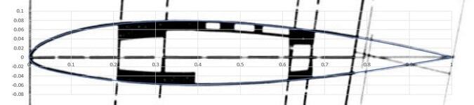
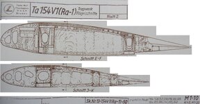
A member on another forum posted some interesting diagrams of the Ta-154. What I'm interested in is the wing profile used, that looks like it had it's thickest part close to the 40% of the chord, at least judging by this picture.
Any volunteers to try to decipher what kind of airfoil was used there?
 
To me it looks more like about 35 % using that drawing.

From a better drawing in Dietmar Hermann's latest Ta 154 book page 77 showing some V1 wing profiles I estimate about 30 % for the inner wing and about 35 % for the outer wing.
It is difficult to determine exactly where the wing is thickest but I think it is slightly behind the front spar.
 
Tracing the airfoil at the aileron/flap junction gives a max thickness of 13.7% at 38% chord.
Airfoil tools gave the closest reasonable aerofoil as the Tempest :)
AF.jpg

AF2.jpg
 

Attachments

  • AF2.jpg
    AF2.jpg
    40.4 KB · Views: 13
Did Kurt Tank base his airfoils on the NACA series, similar to both Heinkel and Messerschmitt?

When I looked into the 109 airfoil, it was stated to be a NACA 2R1. The 2R1 airfoil is a 0012 with a reflexed camber. I found some drawings with sufficient dimensions to confirm that the base airfoil for the 109 is the NACA 0012 (obviously thickness changed to suit) with a custom camber. It would have started as a 2R1, but been customised to suit the desired behaviour.

This Ta154 airfoil has the thickness further back, so it won't be directly based on the NACA 0012 however NACA TN 385 explains how the coefficients were calculated - so it would not be that complicated to calculate the formula coefficients for an airfoil with the max thickness at 38%.
 
Tracing the airfoil at the aileron/flap junction gives a max thickness of 13.7% at 38% chord.
Airfoil tools gave the closest reasonable aerofoil as the Tempest :)
View attachment 710776
View attachment 710778

Where did you get this diagramm? An as a layman I ask why it is similar to the Tempest which was supposed to be a laminar flow profil?
Can you rate this Ta 154 airfoil in terms of drag?
 
Last edited:
The first image is from Airfoil Tools
I expect that all the usual countries were aware of laminar flow airfoils by mid 1940.
The second image is taking a snip of the original image, and then pasting it as the background of a chart in excel. I then tweak the coordinates until it follows the airfoil. Once I have done that, I put it into X-Foil to make the pressure chart smooth and then back calculate the coordinates again. It isn't exact, but should be within a few % of the actual airfoil.

ta154ld.jpg


This is based on Re of 6e6. It hasn't been smoothed out completely, so the drag is likely a bit high. NB X-Foil is quite accurate, but not perfect.
 
That is good information. The 230 series still used the base airfoil from the 4 digit series, just with a variety of cambers.
Has anyone got a copy of an original drawing of any one of those FW airfoils? It would be interesting to compare the camber line with the Ta154 and the 230 original airfoil.

I didn't directly answer the question about the similarity with the Tempest. I would put it down to both Focke-Wulf and Hawker using NACA research from 1939/1940. Sydney Cam and the Typhoon had been sold a pup with the thick airfoil research from NPL not being accurate, and wanted to see information from elsewhere. FW is just a guess on my part, but they moved the airfoil max thickness point back around this timeframe. (They may have got the info from Hawkers as well?)
 
To me it looks more like about 35 % using that drawing.

From a better drawing in Dietmar Hermann's latest Ta 154 book page 77 showing some V1 wing profiles I estimate about 30 % for the inner wing and about 35 % for the outer wing.
It is difficult to determine exactly where the wing is thickest but I think it is slightly behind the front spar.
In the mean time I made a scan of the Ta 154V1 drawing and did pixel counts.

The thickness of the inner wing profile is about 16.7 % at about 31 % chord. That is in the trailing part of the front spar.

The thickness of the outer wing profile is about 14.9 % at about 31 % chord. That is just after the trailing part of the front spar.

The relevant part of the drawing is attached (irrelevant parts whited out), so everybody can do his own measurements:
 

Attachments

  • Ta 154V1 wing priofile.jpg
    Ta 154V1 wing priofile.jpg
    314 KB · Views: 34
The designation on that drawing is "NACA Fw 43016" which seems to indicate that FW have modified the base NACA 43016 airfoil.
Comparing the NACA 43016 with the root airfoil shows they are not the same.
I missed the "Fw". Here is an overlay - it looks like they filled in some of the dent under the nose at the root. As to the other airfoil, its not the tip, as its way too thick.
Airfoil comparison.png
 
What information do you have for the root and tip airfoils on the Fw 189?

I've had a 3-view diagram for the Fw 189, that denoted a pretty thick root profile (NACA 23018?), but I can't find it now to save a life. Will try and post it when possible.
 
Thanks - that's great!

Has anyone ever come across airfoil specifications for the Ju 86, Ju 88 or He 111?
 

Users who are viewing this thread

Back