ALLISON V-1710 CRANKSHAFT

Ad: This forum contains affiliate links to products on Amazon and eBay. More information in Terms and rules

jerryw

Airman 1st Class
114
6
May 28, 2008
Trentham, Victoria, AU
Has anyone got a manual or instruction book that covers one of the late-model Allison V-1710 engines which were fitted with 12 counterweight crankshafts?

This type of crankshaft gets a lot of mention in the Dan Whitney book on the Allison V-12 but there are no photos or drawings of the component.

Apparently, each crankcheek of the shaft has an individual counterweight cast integral with the whole shaft. The counterweights are somewhat odd shaped to provide maximum effect and weight saving.

Any postings of illustrations of the 12-cwt crank would be much appreciated.
 
I work at a shop that overhauls Allisons exclusively as a business. We have both 6 and 12 counterweight crakkshafts and the only difference is the extra set of counterweights. There is NOTHIONG wrong with the 6 counterweight unit, but most people seem to feel teh 12-counterweight unit runs a buit smoother. In reality, they run about the same.

link: Google Image Result for http://www.oldengine.org/members/diesel/duxford/Allison5.jpg
 
Last edited:
Greg, I believe the 12 counterweight crankshaft allowed Allison to raise the maximum revs from 3200rpm to 3400rpm.

The change in smoothness may have been imperceptible, but I wonder if it had a more significant effect on main bearing loading and life.
 
All very interesting, I'm sure but I am still looking for photographs and/or drawings of the 12 counterweight crank fitted to the later models of the Allison V-1710.

The models affected were the F 28/29 (-121/123) or the E 21/22 (-117, -109).
 
Hi Wuzak,

In reality, the Allison 1710 V-12 was designed from the outset for 4,000 rpm. The tractor-pull guys are running them at 4,500 rpm with no ill effects, with both 6 and 2-counterweight crankshafts.

The limiting factor in aircraft is the propeller, which cannot handle 4,000+ rpm reliably. It can take an occasional overspeed, but sustained 4,000 rpm operation would result in a broken propeller balde pretty quickly. At minumum the baldes would be stretched beyond operational limits, and would have to be replaced.
 
Photos of the Allison 12 counter-weight crankshaft:

Allison 12 CW crank 1.JPG


Allison 12 CW crank 2.JPG


Allison 12 CW crank 3.JPG


Allison 12 CW crank 4.JPG


Many thanks to Joe Yancey.
 
According to Joe, the 12cw crank did allow for increased rpm, but not because of improved balancing. In fact, Joe says that the balance was not improved at all. The increased rpm capability came about thanks to the increased wall thicknesses in the journals, which made the whole crank stronger and stiffer (and heavier).
 
Many thanks to Wuzak for some great pics. I was beginning to think the 12 cwt crankshaft was a myth! So, now we know - there were four symmetrical counterweights and eight skewed.

Anyone interested in some more info on the 12-cwt crank should download a copy of US Patent No. 2,419,274 from the USPTO website. This patent was written by the designers of the component (McDowall Gerdan) and therefore gives some insights into what they were trying to achieve.

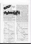
Below, is a page from the SAE paper by Dim. Gerdan on the Allison late developments. The graphs show the advantages conferred by the 12 cwt crank on bearing loads and crankcase stresses.
 

Attachments

  • SAE Gerdan p99.jpg
    SAE Gerdan p99.jpg
    102 KB · Views: 419
V1710 12 cwt ERROR.jpg


Here's a little puzzle to finish up this thread.

Above is a drawings page from a very long and detailed report by Allison engineers on the 12 counterweight crank.

The top pic is a side view of the whole crankshaft and below it are individual drawings of each of the crankcheeks and counterweights as seen from an end view of the shaft, ie, seen from "Arrow X".

Can you spot the blooper??
 
Last edited:
Well done, Mr Wuzak. Got it first time. Give the man a prize!

Yes, there is something peculiar regarding the top drawing. If the No. 1 and No. 6 crankpins are pointing upwards, then all the others should appear below the centre line, as indicated by the crankcheek drawings underneath.

Hard to explain.

It's not uncommon that objects in drawings that are out of plane are shown in plane. In doing that, if the middle 4 cylinders were all pointing down that would make it look like they were all at the same angle, so the middle 2 are moved up to make it clear they are different.

The cross sections appear, to me, incorrect. But If the left bank is numbered 1, 3, 5, 7, 9, 11 front to rear and the right bank is numbered 12, 10, 8, 6, 4, 2 from front to rear then I believe they are correct.
 

Users who are viewing this thread

Back