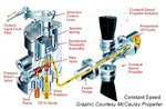
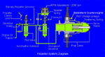
I'm trying to find out how the internal planetary gear sytem works in the variable pitch gearbox for the propeller. I have limited information and a sectional view but with little detail. If anyone could explain it to me or direct me to someone who might know it would be most appreciated. I do have the maintenance manual for the VDM prop but it gives no explanation of the internals.
Thanx and have a Merry Christmas!!!
Thanx and have a Merry Christmas!!!