Navigation
Install the app
How to install the app on iOS
Follow along with the video below to see how to install our site as a web app on your home screen.
Note: This feature may not be available in some browsers.
More options
You are using an out of date browser. It may not display this or other websites correctly.
You should upgrade or use an alternative browser.
You should upgrade or use an alternative browser.
Consolidated LB-30/B-24A/MkI/II Liberator engines
- Thread starter Shessi
- Start date
Ad: This forum contains affiliate links to products on Amazon and eBay. More information in Terms and rules
More options
Who Replied?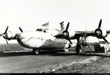
Actually not a disk but a cover. It looks like a kind of protection of the valve tappets and the ignition system. Also possible the part could be used to increase the airflow speed for a better cooling in the NACA engine cowling.


the pic source: the net.
the pic source: the net.
- Thread starter
- #3
Many thanks W.
Not seen that first close in pic, which is great, but have the second one.
TBH I doubt it is to cover those items you mention, as the tappets are at the other end of the cylinders ie the top, also all the ignition wiring would be in metal conduit piping to protect it.
I had a thought of something like cooling reduction, but your thought of air flow acceleration to aid cooling, is an interesting and more likely one. Certainly the second pic is of Lib MkII's in North Africa, where more cooling would be good!
You may well be right with the things you've said, it's just needing hard evidence about those discs/covers etc
Cheers
Shessi
Not exactly regarding the valve tappets ... the front "star had them in front of the cylinders at the side of it. It should be kept in mind that the early B-24 were poered by the Pratt & Whitney R-1830-33C-4G engines. So possible that there were other engine devices attached to the front and hidden under the cover.
But I agree , the air flow acceleration to aid the cooling seems to be the most likely.
But I agree , the air flow acceleration to aid the cooling seems to be the most likely.
Simon Thomas
Senior Airman
They seem to have some thickness to them, and a pipe from the outer edge back to the prop shaft. My guess would be propeller de-icing fluid.
If it were just for air flow deflection, why would it be so thick?
If it were just for air flow deflection, why would it be so thick?
- Thread starter
- #7
Hmmm thanks S, that's a good call about de-icing, so possibly some form of thin circular tank, which feeds to the blades. You can see small pipes or wires coming out of the disc in the close-up pic.
I have to agree that it's not that thick, and would have be of a curved design to allow smooth airflow around it, to promote faster airflow.
Another intial thought I had was, if it did have weight to it, could it be an engine or prop vibration damper?
Something I've noticed is that there is a difference between discs in the pics of the LB-30/B-24A engine to the Lib MkII's. The Lib MkII's appear to have a lip or seam running around the circumference where the LB-30/B-24A engine disc doesn't?
Some time ago I emailed the C.A.F about this query, as their B-24 Diamond Lil was an LB-30, with these engines and the discs. The old gal isn't fitted with these now, so either they've removed them or changed to a diffent engines. Unfortunately they haven't replied to both of them.
Keep 'em coming....
Cheers
Shessi
Last edited:
I can't remind myself if the LB-30/YB24/B-24 had the de-icing system for props. Perhaps it didn't because these even did't have the de-icing system for wings and the tail contrary to the later variants of the B-24. Also I would like make a focus on that the Consolidated (Model 31) XP4Y-1 Corregidor NX-21731 had them too although in a couple of shots it can be noticed that initially the disk ( cap ) was attached to the port engine only. I doubt the designer could have attached the de-icing system to one engine only while the second one could be without.


the pic source: the net.
the pic source: the net.
ThomasP
Senior Master Sergeant
I have read about a propeller deicer system that might be what is in the photos.
IIRC the description said that the deicer fluid tank was in the form of a flattened donut and was located/attached directly behind the propeller hub assembly. The piping led to grooves in the propeller that allowed the fluid to flow via centrifugal force out onto the propeller blade. It also mentioned that the tanks could not be left in place if operating in tropical temperatures. Unfortunately there were no pictures with the description.
Maybe?
ThomasP
Senior Master Sergeant
I will try and remember where I ran across the description, but it was a long time ago - I think in the mid-1990s.
ThomasP
Senior Master Sergeant
There is a method that uses what are called 'slinger rings' to help disperse the deicer fluid to the propeller blades - but they rotate with the propeller. However, it does not look to me as if the objects in the above photos rotate with the propeller, and the piping does not look as if it is in the right position to disperse the deicer fluid directly onto the blade.

Here is LB-30 Liberator B.II crashed at Salbani, India in 1943 while with 159 squadron. Those fittings still seem to be in place despite the personnel wearing shorts and sola toppees.It also mentioned that the tanks could not be left in place if operating in tropical temperatures.
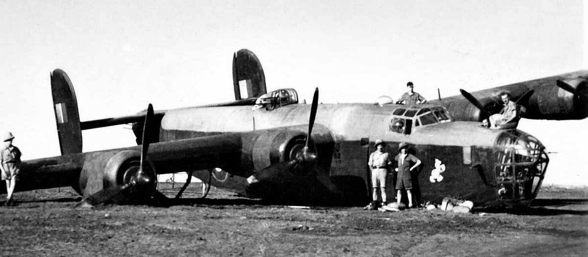
Liberator II AL564 [Royal Air Force Aircraft Serial and Image Database]
This is a individual page for Aircraft Liberator II AL564 of the Royal Air Force. You may find some details of its career, loss details, maybe a photograph, and whatever mention of the serial that occurs in the forum. At the very least you will end up knowing what type of aircraft carried this...
www.rafcommands.com
Bit like the photo in post #2 above.
ThomasP
Senior Master Sergeant
I looked around a bit more, and found the objects in question on a lot of photos of the LB-30. As pointed out by EwanS they were present on the Liberator Mk II in India, and I found the objects on BOAC LB-30s used in the Air Transport Ferry system (Return Fery Service) in the North Atlantic.

Last edited:
- Thread starter
- #17
Hi Folks,
Thanks W for the XP4Y-1 pics, yes same engines, and obviously they were messing around with various things, so we can take it, normally all engines would be fitted with them. Also thanks ES for the BII pic.
TP, many thanks for taking down this route, I really think this makes more sense. At another site i posted this, someone kindly posted this more detailed pic of the system.

As W says the discs look diffent to the slinger ring system, but I've just had a thought. What if the discs on the LB-30 engines were in fact covers for the slinger rings?
We're pretty certain these discs do not spin. So are these are un-spinning covers fixed to the crankcase, for the slinger ring de-icing system, that is attached to the hub and spins inside?
Thoughts?
Shessi
Thanks W for the XP4Y-1 pics, yes same engines, and obviously they were messing around with various things, so we can take it, normally all engines would be fitted with them. Also thanks ES for the BII pic.
TP, many thanks for taking down this route, I really think this makes more sense. At another site i posted this, someone kindly posted this more detailed pic of the system.
As W says the discs look diffent to the slinger ring system, but I've just had a thought. What if the discs on the LB-30 engines were in fact covers for the slinger rings?
We're pretty certain these discs do not spin. So are these are un-spinning covers fixed to the crankcase, for the slinger ring de-icing system, that is attached to the hub and spins inside?
Thoughts?
Shessi
ThomasP
Senior Master Sergeant
I do not think it can work that way. If I am visualizing things correctly, since the slinger ring and the slinger tubes rotate with the propeller hub, if the object(s) in question do not rotate they would sever the slinger tubes. And if the objects do rotate they would sever (or seriously displace) the slinger feed tube.

Last edited:
- Thread starter
- #19
Tom,
You make perfect sense...damn! ha!
Thanks for indicating it clearly, I did have doubts of how my idea would work.
So then, the discs are local (to the slinger ring) de-icing fluid supply tanks. If so, are they 'topped-up' from a larger wing tank? And if so, why have another tank in the system, why not just be fed directly from the wing(?) tank?
Shessi
p.s Nice enginering background there. And maybe not a PITA, more like 'annoyingly correct'...")
You make perfect sense...damn! ha!
Thanks for indicating it clearly, I did have doubts of how my idea would work.
So then, the discs are local (to the slinger ring) de-icing fluid supply tanks. If so, are they 'topped-up' from a larger wing tank? And if so, why have another tank in the system, why not just be fed directly from the wing(?) tank?
Shessi
p.s Nice enginering background there. And maybe not a PITA, more like 'annoyingly correct'...
- Thread starter
- #20
A small bit of info. Someone else has informed me that the B-24 de-icing fluid tanks were either 6 galls or 21 galls, situated under or behind the flight deck. But no info on the discs possibly being part of this system.
I have also just emailed the C.A.F again, the third time, about Diamond Lil, and if there is anyone who could help.
Shessi
I have also just emailed the C.A.F again, the third time, about Diamond Lil, and if there is anyone who could help.
Shessi
Users who are viewing this thread
Total: 1 (members: 0, guests: 1)