Defining and explaining "Corner Speed" (1 Viewer)

Ad: This forum contains affiliate links to products on Amazon and eBay. More information in Terms and rules

drgondog

Major
9,420
5,854
Jun 28, 2006
Scurry, Texas
We have recently experienced Troll invasion - one of which is the worst dabblers in the less than arcane arts known as "Aircraft Performance", with subchapters in throttle management, "prop disk loads changing the wingload in non-linear ways", etc.

All interesting topics and equally worth discussing - but this thread is about the huge dissemination of blivet on the subject of CORNER SPEED.

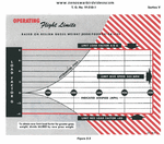
The first diagram is the Corner Speed Diagram prepared by North American Aviation to insert into the P-51D Pilots Handbook. Note carefully the message at the bottom which states that the Corner Speed calculation is for 8,000 pound Gross Weight and that the G load allowables for each condition must be factored by GWactual/64000 pounds.

Note the 'accelerated stall' area sets one boundary of the lower speed threshold.. so a 3G sustained turn at 160mph at 8000 pounds on the deck is on the threshold for departure but not structural limit and not corner speed. Note that at 6G the sustained turn at ~230mph is at stall but NOT Corner Speed. Note@ 8G at ~ 260 mph at 8000 pounds at sea level the airframe has reached CORNER SPEED.


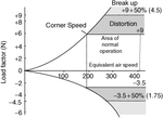
More later - but Note for the second (conceptual) diagram that the Corner Speed at ~ 195mph is at the 6 "G" load for Design Limit and that Distortion (non elastic deformation) begins and continues until Ultimate Load Factor (9. =50%) or 13.5G is reached and complete catastrophic failure is predicted. BTW I have no idea why the left value indicators for 6G load has a +9 on the far right

I suspect they meant to either have 6G load factor with a +6 on the right and a +6+50% (3.) on upper right to be consistent.
 

Attachments

  • P-51 load chart and POH.gif
    P-51 load chart and POH.gif
    39.7 KB · Views: 1,295
  • corner speed diagram.gif
    corner speed diagram.gif
    7.9 KB · Views: 1,270
Last edited:
From one of my sources - "The lowest air speed at which a fighter can pull structural or aerodynamic limiting" Which tells me either I'm going to stall or break the plane (or both) when I hit this number. Spot on Bill!
 
So, while the G forces are shoving you head down into your arse, you have to worry about the airplane either falling apart or stalling out?

Forget the muggers, that is one corner I'll avoid at all costs.
 
I noticed that the two graphs are slightly different. The one on from the flight manual shows indicated airspeed and the other one shows equivalent airspeed. I would guess the one from the flight manual would have some altitude definition although I don't see one.
 
So it defines the horizontal repercussions (distortion/breakup), but what about the vertical post 505mph? Mach tuck? I was under the impression that many ww2 fighter airplanes easily exceeded 550-575mph before recovery was not possible (again altitude dependent).
 
i would worry more about breaking apart than stalling ( unless you dont have enough alt to recover). with stalls you are usually trying to make the plane fly where it doesnt naturally want to....in a steep turn...pulling back too far on take off, etc. usually get a warning ( a shutter if not a blaring horn) and most of the time can recover by simply dropping the nose, slacking off on the stick, adding power, etc. to where the ac rights itself. a lot of the situations where you reach the point of structural failure are more towards the opposite. you are trying to force the ac in a direction different than it naturally wants to go at that point in time. generally it has gotten away from you and is now being flown more by the by the laws of physics than you. you compound the situation by adding higher G forces trying to recover. i.e. you are at 7000 feet and in a steep screaming in a dive going 500+ mph. many a plane has lost its wings in type of senario...
 
have been reading these posts (on the other thread) with amusement.

On one side when a post mentions "thrust in a curve" the poster has moved above Isaac Newton in laws of motion.

On the other side any talk about an aircraft in a curve is complete theory. The weight of a plane is not a constant, unless the oil and fuel tanks of the plane are dirctly on its centre of gravity and centre of lift then its performance is not a constant. The lift of a planes wings are a general value, a plane in a turn has two wings doing two speeds form one extremity to the other and the airflow is not completely straight.
 
have been reading these posts (on the other thread) with amusement.

On the other side any talk about an aircraft in a curve is complete theory. The weight of a plane is not a constant, unless the oil and fuel tanks of the plane are dirctly on its centre of gravity and centre of lift then its performance is not a constant. The lift of a planes wings are a general value, a plane in a turn has two wings doing two speeds form one extremity to the other and the airflow is not completely straight.

Very True (although d/dt (mV) will take care of the change in mass with respect to time with greater precision than the change in Velocity for all the other reasons mentioned -

I think I mentioned in another thread that 'perfect circular' motion in an aircraft is an abstraction, due to the effects of turbulence, indicial gusts, unsteady control response to random inputs, total inability of any pilot to maintain a perfect combination of rudder and elevator and aileron responses to the aerodynamic loads, the areoelastic response to the loads changing local angles of attack, the increasing vortex drag due to the high angle of attack required for a banked mid to high G turn, etc, etc , etc.

On the other hand if you wish to assume the same perfect fluid and perfect pilot to deal with the airplane in its own frame of reference, the equations are reasonable when you strip small percent contributions like incremental vortex drag of the fuselage/wing root, epennage in the prop stream tube, the trim drag, etc, etc as well as assume oswald efficiencies, prop efficiencies, tip losses, etc - then the equations derived from F=ma work pretty well

The same may be said regarding structrural analysis of complex materials, complex geometries, and wide range of 'steady', transient and reversible loads.. but we did the best we could.

So, the combination yields guidelines like "V-n" charts presented above

Your improvements to the foundation equations contained in most "introductions to flight' would be welcome. Pitch in. or not. as you choose... but if you fly, ignore the "V-n" chart which uses those equations and methods at your peril.
 
Last edited:
have been reading these posts (on the other thread) with amusement.

On one side when a post mentions "thrust in a curve" the poster has moved above Isaac Newton in laws of motion.

On the other side any talk about an aircraft in a curve is complete theory. The weight of a plane is not a constant, unless the oil and fuel tanks of the plane are dirctly on its centre of gravity and centre of lift then its performance is not a constant. The lift of a planes wings are a general value, a plane in a turn has two wings doing two speeds form one extremity to the other and the airflow is not completely straight.

While you have a point - how else do you show this pictorially so it could be placed in a flight manual? Let alone to be flown by a 21 year old 2Lt?
 
So it defines the horizontal repercussions (distortion/breakup), but what about the vertical post 505mph? Mach tuck? I was under the impression that many ww2 fighter airplanes easily exceeded 550-575mph before recovery was not possible (again altitude dependent).

First comment on last sentence.. there were many instances of IAS in that range, few even remotely close for TAS. Pitot tube type Instruments didn't work worth a damn in compressibility range

Matt - the chart is independent of axis of reference per se. Having said that, the 'stall region' defined as 'accelerated stall' is usually associated with a lateral manuever such as a banked turn - but you can stall also in a dive pullout and mush your butt into the ground.

The curve is calculated with the same Vmax equations I presented to Gaston.

The 505mph is the plackard 'do not exceed' velocity and that is all about the Q loads on the airframe.. i.e if you could strap a J-79 on this 8000 pound Mustang - it would go fast but not far.

The Pony started the drag rise around .65 M, the placard was for .75 and the highest achieved in dive was .83-85M depending on the belief system around the instruments. What happens in that regime is that the combination of parasite drag and compressibility drag go way up, very rapidly. At some point between .8 and .9M at 1G things that once were attached are no longer attached to the airframe due to the stresses caused by extremely high dynamic pressure loads.

There was a 1G 'mach tuck' per se in the 51 which resulted in heavy stick forces, but much less than P-47/P-38/F4U, and never resulted in the strong negative pitching moment near Mcr that other WWII fighters encountered.

Theoretically the laminar flow airfoil had serious advantages to delayed drag rise.
 
From one of my sources - "The lowest air speed at which a fighter can pull structural or aerodynamic limiting" Which tells me either I'm going to stall or break the plane (or both) when I hit this number. Spot on Bill!

Thank you Joe - and we are reminded that the 'limit line' is smooth, non vertical indicial gusting, air...this is not the line you fly in a glider over the Rockies or searching for a thermal around a Texas Killer.

In other words, if we ignore this, we are smited mightily and seek comfort in silk - if available..
 
I noticed that the two graphs are slightly different. The one on from the flight manual shows indicated airspeed and the other one shows equivalent airspeed. I would guess the one from the flight manual would have some altitude definition although I don't see one.

Dave - I pulled from two different sources - one from TF-51D Manual and the other 'generic' - but I liked the generic simply because it helped explain what happens when you exceed Limit load and head toward Ultimate (and kiss your ass goodye) load.

There was no point I was making in showing one with IAS in mph and the other in EAS. I reality the 'IAS" as near as I can tell is TAS in reality for SL.. when i did the Vmax calc for a 51D@8000 pounds at SL I got ~250mph at 8g for the corner speed. I suspect the difference is what NAA used for CLmax versus mine based on level flight stall while reducing velocity at 1Kt/sec. If NAA had less than 1.72 that would explain the slight difference between their graph and my calc

EDIT - I tried CLmax=1.6 and it yielded 259 mph at 8G @8000 pounds on the deck... which seems very close to the manual chart..
 
Last edited:
Dave - I pulled from two different sources - one from TF-51D Manual and the other 'generic' - but I liked the generic simply because it helped explain what happens when you exceed Limit load and head toward Ultimate (and kiss your ass goodye) load.

There was no point I was making in showing one with IAS in mph and the other in EAS. I reality the 'IAS" as near as I can tell is TAS in reality for SL.. when i did the Vmax calc for a 51D@8000 pounds at SL I got ~250mph at 8g for the corner speed. I suspect the difference is what NAA used for CLmax versus mine based on level flight stall while reducing velocity at 1Kt/sec. If NAA had less than 1.72 that would explain the slight difference between their graph and my calc

EDIT - I tried CLmax=1.6 and it yielded 259 mph at 8G @8000 pounds on the deck... which seems very close to the manual chart..

I didn't think you were trying to make some point. I was curious and just pondering the difference between IAS and EAS in the chart. No pilot uses EAS for anything. It is primarily a design tool to estimate vehicle performance. Calibrated airspeed, equivalent airspeed, and true airspeed, and, if no wind, ground speed, are all equal at SL standard day. Indicated airspeed will vary slightly due to installation and position error.
 
I didn't think you were trying to make some point. I was curious and just pondering the difference between IAS and EAS in the chart. No pilot uses EAS for anything. It is primarily a design tool to estimate vehicle performance. Calibrated airspeed, equivalent airspeed, and true airspeed, and, if no wind, ground speed, are all equal at SL standard day. Indicated airspeed will vary slightly due to installation and position error.

All true - the only aspect of it that I cared about was the nice representation of the bad things that happened when moving from limit to ultimate load - that would have been the point.

As an aside the EAS=CAS*Sqrt{rho/rho@sl} to reduce all calibrated airspeeds at different altitudes to a standard of values that people (engineers) can use and know exactly what everyone means.
 
ww2 fighter airplanes easily exceeded 550-575mph before recovery was not possible (again altitude dependent)

I would add, how many aircraft could exceed those speeds if not from a steep dive from high altitude?
a shallow dive?
In most test dive charts, it's revealed that most fighters had to be dove from 35-40K feet and 550-575 TAS was probably a more realistic top speed than the presumed 600+ mph touted in previously published assessments.
maybe the late Spitfire from used in the mid 50s, but nothing from WW2.
There was a 1G 'mach tuck' per se in the 51 which resulted in heavy stick forces, but much less than P-47/P-38/F4U, and never resulted in the strong negative pitching moment near Mcr that other WWII fighters encountered.
The stick force of the P-51 was actually heavier according to some tests between the FG-1 (8lbs), P-47(12lbs) and P-51(20lbs).
That has more to do with the context of the stick force described.
A P-47 in compressibility would obviously have more issues, though other than descriptions of the stick having the feeling of being set in cement, their were also the tests where it was not an issue of force, but an issue of response, because the pilot could pull full deflection but there was a disruption of the airflow over the elevators.
It has been argued that the heavy stick force was worked into the design of the P-51 to keep pilots from over stressing the aircraft, and in some ways the heavier stick force allowed pilots to better gauge aircraft limitations.
The P-51 was initially quite flawed when it came to mach tuck vs control force, where the P-47 was generally considered better suited for similar types of dives, being more structurally sound for the uncoordinated effects of mach tuck. It was eventually learned that a primary cause for the tuck was the pilots tendency to throttle back in the dive, increasing the drag therefore increasing the tuck.

They did manage to better engineer the later P-51Ds to manage the tuck and trim effects encountered in a dive.
In the dive, there is a nose up tendency, which the pilot would normally counter with trim. If the pilot encountered tuck he would let out trim to hold the angle of dive, but in the absence of tuck the nose would want to pop back up suddenly. The retooling of the elevator throw involved easing the stick force so the pilot was less reliant on trim and could simply use a moderate amount of stick forward to hold the dive.
 
I would add, how many aircraft could exceed those speeds if not from a steep dive from high altitude?
a shallow dive?
In most test dive charts, it's revealed that most fighters had to be dove from 35-40K feet and 550-575 TAS was probably a more realistic top speed than the presumed 600+ mph touted in previously published assessments.
maybe the late Spitfire from used in the mid 50s, but nothing from WW2.

505 mph (TAS) was the placard for the P-51. greater speeds were obtained in very risky terminal dives up to measured .83-.85 Mach and every aircraft was 'bent' to a degree.

The stick force of the P-51 was actually heavier according to some tests between the FG-1 (8lbs), P-47(12lbs) and P-51(20lbs).

I read that (1989 Experimental Test Pilot Report) and it flies in the face of many opposites POV as well as my own (limited) experience so I wonder. The America's 100,000 by Dean said exactly the opposite among a group of 20+ test pilots convening at Patuxent River in October 1944 and they ranked all of the primary US Fighters. My own experience (never in a terminal dive but in the .7 + M range did not yield high stick forces or a pronounced tuck, but the bird did yaw to the right - controllable with rudder but rudder pedals stiff. I have read excerpts of the 1989 Experimental Test Pilot Report and have serious doubts about the conclusions. One of my biggest issues is only one pilot flew all a/c at reduced loads and reduced engine powerplant. We are back to anecdotal discussions and I prefer 20+ anecdotes to one.


That has more to do with the context of the stick force described.
A P-47 in compressibility would obviously have more issues, though other than descriptions of the stick having the feeling of being set in cement, their were also the tests where it was not an issue of force, but an issue of response, because the pilot could pull full deflection but there was a disruption of the airflow over the elevators.

The P-47 also had a pronounced tuck near compressibility - distinctly like the P-38. I did not not have the same sense in my time in a 51 but I did not push to ultimate Mcrit, although I was in the Drag rise region >.65M. I found the control forces very responsive up to 300-350kts TAS.

It has been argued that the heavy stick force was worked into the design of the P-51 to keep pilots from over stressing the aircraft, and in some ways the heavier stick force allowed pilots to better gauge aircraft limitations.


A reverse rudder boost was introduced to make it difficult for the pilot to put too much input (stiffer rudder pedal response) during the yaw in dive... basically all -20 late production and retrofit into all D's, Aileron response on the other hand was improved from the original XP-51 with sealed and balanced ailerons in the P-51B forward. Ailerons were stiffer >300Kts but not so stiff as to make the airplane unresponsive.

Read all the test pilot reports from WWII to gain a better sense of their reactions to the Mustang controllability


The P-51 was initially quite flawed when it came to mach tuck vs control force, where the P-47 was generally considered better suited for similar types of dives, being more structurally sound for the uncoordinated effects of mach tuck. It was eventually learned that a primary cause for the tuck was the pilots tendency to throttle back in the dive, increasing the drag therefore increasing the tuck.

That would be incorrect relative to the 51. What sources led you to conclude that? First the laminar flow wing for all its failures to achive true laminar flow, did display superior response in drag rise through Mcrit. Second, the Mustang did not 'tuck' relative to P-38 and P-47 probably due to the delayed onset of Mcrit and the location of separtation on the airfoil.

The Mustang and the P-47 and the P-38 were all initially designed to 8G limit/12 G Ultimate - no difference. The P-47 was restricted to .75 Mach as the P-51 and thye P-38 was limited to .68M


They did manage to better engineer the later P-51Ds to manage the tuck and trim effects encountered in a dive.

The two design changes to improve dive pullout response were a.) changing fabric covered elevators to metel ailerons and b.) decreasing the horizontal stabilizer incidence from 2 degrees to 1/2 degree - both reduced the required stick forces to recover, but the incidence change required more nose down trim input in lower speeds.

In the dive, there is a nose up tendency, which the pilot would normally counter with trim.Not with a 51 - if you input nose down trim during the dive, you would experience even greater loads on the elevator/Stab during pullout. The training emphasizes stick and rudder control and leave trim alone.

If the pilot encountered tuck he would let out trim to hold the angle of dive, but in the absence of tuck the nose would want to pop back up suddenly. (That is exactly why you don't input 'up' trim in a dive The retooling of the elevator throw involved easing the stick force so the pilot was less reliant on trim and could simply use a moderate amount of stick forward to hold the dive.

If the Mustang had a 'tuck' issue it certainly did not experience a 'nose up' issue. Nose up (pitch forces) would normally be a result of CM changes due to a near complete loss of airflow over the wing. In that mode the horizontal stab would have a negative lift component causing the nose to pitch up - but that wasn't an issue in the 51 (to my knowledge).

Near Mcrit the issue was a rearward movement of the aerodynamic center aft, causing a nose down moment coefficient CM to dominate (i'e. P-47 and P-38).

The Mustang Manual had specific warnings to NOT use trim to recover form a dive
 
Last edited:
That would be incorrect relative to the 51. What sources led you to conclude that?
In reading up on compressibility dives of the P-51 and P-47.
It was the thickness of the wing and structural strength, not so much the drag profile. You are also aware of that Mustangs had varying wing thicknesses and that also had much to do with the structural integrity.

The behavior is also outlined in manuals for both aircraft, where in the late P-51 manual it describes the adjustments made for better high speed control under critical mach conditions. Now that you mention it, it may have been the changed incidence to allow for better stick force during high mach speeds. I dont remember the specific parts only that it is specified in the later D manual.

Nose up (pitch forces) would normally be a result of CM changes due to a near complete loss of airflow over the wing
In the context of my description, mach tuck requires the pilot to counter the increased nosed down force of the aircraft. He does this with stick, or with trim. In mach tuck, he has to pull up to hold the angle of dive.
You can imagine that shifting tendencies of the aircraft can become quite cumbersome.

Again there is a better description in the late mustang manual, that describes both the improvement and behavior of the aircraft.


Bill
 
Bill - do you know what causes a "mach tuck"? It is caused when the shock wave forms and moves aft, changing the aerodynamic center of the wing.

Most conventional wings with an aft tail have a wing airfoil with negative value for Moment Coefficient (counterclockwise) about the aerodynamic center. This is normally balanced by a conventional horizontal stabilizer/elevator combination which produces lift in down direction to offset the CMac. When that wing lift is disrupted, it contributes to the pitch down moment about the 1/4 point and tends to overcome the stab/elevator contribution until significant additional tail down force is created by up elevator or trim

Additionally when a shock wave initiates, the flow separates earlier and the resulting reduced lift also reduces positive moment about the Cg, as well as reduces the relative angle of attack of freestream hitting the stab/elevator. This reduces negative lift at the tail and further pitches the nose down. In fact it is the latter condition which occurs first and was first discovered on the P-38 (at least for US).

This phenomena is referred to as a Mach Tuck. Different airfoils have varying magnitudes of CMac, all generally negative, and generally independent of AoA for normal flight profiles.

What made the Mustang modified laminar flow wing 'different' is that it's max thickness is around 40% chord where the Jug and P-38 (and Me-109 and Fw 190) had max T near the 1/4 chord point.

The Aerodynamic center for all of these airfoils (and the Mustang)were near 1/4 point.

As the flow over the top of the wing reaches M=1, it happens first at max T of the airfoil. When that happens to a conventional 1/4 Chord maximum T, it also happens to be close to the a/c... for a Mustang however, M=1 around 40% chord and the onset, despite the fact that the 51 had a medium 'thick' airfoil, was delayed to a higher Mcrit than would exist for a conventional airfoil of the day.

Another interesting feature of the shape of the Laminar flow designs is that they very much resemble the supercrit airfoils which are designed with max thickness even closer to the trailing edge.

I'll dig up the NACA report that outlines the delay to critical separation and movement of shockwave that was inherent in the Mustang's modified laminar flow wing

As to 'varying wing thickness' - true but for both the Mustang and Jug (and virtually all WWII and beyond fighters) ALL varied 'wing thickness' spanwise but maintained the ratio of thickness to chord spanwise by virtue of wing taper out to wing tip area. Most wings were designed with a 'thinner t/c" at the tip to try to reduce induced drag/tip losses.
 
Last edited:
Bill - do you know what causes a "mach tuck"? It is caused when the shock wave forms and moves aft, changing the aerodynamic center of the wing.

exactly.
I don't see how anyone could be a fan of aviation, particularly WW2 fighters, and not have an understanding of mach tuck.
There are also some other contributing factors to the actual tuck, which may not actually be related to compressibility but instead the actual drag profile of the aircraft and how the air screw distributes air over the wing.
If the pilot throttles back the slowing airscrew and this causes more drag. It was found that pilots could recover from tuck by increasing throttle in the dive, where decreases would cause a more severe tuck. Again, this is also outlined in the manuals, particularly in later manuals where they may have had a better understanding of emergency procedures and compressibility.
In reviewing a Wright Field test for the P-47 dive flaps, the amount of tuck was from 65 to 67 degrees,(4 seconds of dive) a mere 2 degrees. It may have steepened more if the pilot had not deployed dive flaps, but also test pilots may have also had a better understanding in how to combat mach tuck or to minimize its effects.
Pilots were advised to start dives with medium amounts of throttle so that increases could be made in the dive.

As to 'varying wing thickness' - true but for both the Mustang and Jug (and virtually all WWII and beyond fighters) ALL varied 'wing thickness' spanwise but maintained the ratio of thickness to chord spanwise by virtue of wing taper out to wing tip area.

I know the Mustang had specific variants with thinner wings and lower load limits. Its apples to oranges when comparing them to the wing thickness of the P-47, i only mention it because perhaps my reading was not in the context of the P-51D which had higher load limits and wing thickness than previous variants. So saying the P-47 was better suited to handle mach tuck, may not have included the P-51D.
It doesn't take long to find several examples of P-51 pilots diving from 20k ft in vertical dives while chasing or eluding enemy aircraft. It was certainly a very capable fighter in that capacity.
 

Users who are viewing this thread

Back