Drag of radial-engined fighters (1 Viewer)

Ad: This forum contains affiliate links to products on Amazon and eBay. More information in Terms and rules

Reading the 'America's hundred thousand', one can find two different Cd0 values for the P-47. One being 0.0213 (pg. 113), another one being 0.251 (pg. 598 ). Ie. the 1st value is in the ballpark with Spitfire (single stage engine) or P-39, another one seem much more believable. IIRC The Fw-190A (A-3?) was credited with CdO of ~0.0245.
I'll ask people to share their data here, about all radial-engined fighters :)

Tomo - there are a couple of points regarding Dean's values. First the ,0213 value for pg 113 and pg 592 are for the P-47B, whereas pg 598 zero lift incompressible parasite drag of .0251 is for P-47D. In Dean's Performance tables all the CDo are THEORETICALLY those for 250 mph at 10,000 feet - but unless you read the reports and look at Drag vs RN for the Validated Wind tunnel tests, you will never know.

Dean does not specify the RN, which is crucial for RN of < 20 Million based on Mean Aero Chord. For the value .0176 for the P-51D, the reference report NA Report NA-46-130 dated 2/6/46 presents CDmin = .0174 at RN=2x10^^6 which for MAC of 6.63 ft is about 146mph (I'll have to double check). If you look at the Drag vs RN chart for the P-51D, you will see that his .0176 value does NOT include racks, surface roughness, leaks, gun ports. When you add those factors, the actual CDo rises to .0192 at 2X10^^6 RN. Without Racks, the CDo is .0185


At 250 mph at SL, the RN=~15.4x10^^6. If you go to page 112, Graph 11, you will see that the Cdo drops from a high value on LH side of 2x10^^6 to a steady state value for RN>20x10^^6. This chart seems to be the P-51D total Drag (incl everything but racks) at SL, from the report he references.

At 10000 feet and 250mph the CDo for the P-51D from that report is close to 11.3 x10^^6. At that altitude and TAS for the P51D absolutely clean (no racks) the CDo= ,0165.

With Racks = .0173 which is close to the value he uses (I could also be off on the interpolation) for the P-51D.

He made a comment that typical WWII fighter RN's were in the 5-8million range - not so, they were above 20 million for medium high speeds.

Summary - If we take all the values from Dean's 100,000 as values for CDo at 250mph and 10,000 feet as correctly extracted and normalized to the specific RN for each fighter at 250/10K based on their MAC, then the numbers seem rational.

PS - I agree with Timppa that the .0215 CDo is Not for the P-47D. For similar reasons I do not believe the F8F CDo at 250mph/10K is below .025 in combat condition with a NACA 23018 wing.
 
Last edited:
The P-51D report is buried page by page in the Smithsonian P-51 Mustang drawings collection in the Misc Folder. Mike Williams has the Summary pages but that doesn't include the drag discussion which is quite detailed. I will look to see if I can get the others.

After I posted yesterday I really dug into the Performance estimates of the report and am satisfied Dean reproduced the correct Total Drag from the Graphs/plots of Total Parasite Drag vs Reynolds Number. That said, you also need Induced Drag to get to Total Drag. You also need to apply Compressibility factor.

His Graph 12 seems to be an accurate reproduction of the P-51D Compressibility Drag rise as a function of Mach No. Because of the laminar flow wing the drag rise for the Mustang is less, particularly in the .5M-.65M range, than all the other fighters except perhaps the P-63 (I have not seen the plots but the P-39 was pretty bad). At 250mph, 10K feet all the fighters are at 0.34M. The Compressibility factor is about 3% so Parasite Drag = (CDo)*1.03.

Thus, the tables for Flat Plate Drag are understated as he does not include Compressibility or Induced Drag.

The Spit, P-38 and P-47 all have better Induced Drag properties based on either plan form (Spit/P-47) or Aspect Ratio (P-38 ~ 8.24 vs 5.81 for P-51).

Also, his later tables include values for acceleration and while his approach for Thrust is valid as presented on pg 99, it is Not Total Thrust as it does not include incremental thrust from engine exhaust. Nor is it applied to Total Drag, only against CDo from the uncorrected Parasite Drag vs RN.

GregP spent a lot of time over the years compiling Drag data and values for different fighters from many reliable sources but I was never able to get my arms around his table because of the factors enumerated above.
 
Short answer Tomo, is that the detailed report for the P-51D is not available (so far) but the summary is on Spitfireperformance.com. I will start looking for the rest
 
Hi Bill!

I have a lot of data, as you said above, but the places where I got it didn't provide the necessary qualifying data for assessing the drag coefficients. From the way the essential data are neglected, it would seem to me at this late date that the people who put the various data tables together had an agenda ... probably to support their own choice for "best fighter."

So the data I have seem to be all equally useless except as a broad comparison. I've seen information that says the P-47 should have much higher drag than many other fighters, but it turns out to be one of the fastest fighters of the war in the real world. Late models were good for 470+ mph and an experimental version did 504 mph. That's somewhat inconsistent with what I'd have expected if the flat-plate numbers are to be believed.

I'm taking drag coefficients with a large dose of skepticism these days unless the supporting data are also available. I may start trying to collect then again when I get time away from teaching duties.
 
Last edited:
Nothing to disagree with above.

You know from your own experience at Reno and POF that HP (Lots) overcomes drag as it is converted to thrust (more) with each incremental engine improvement in the same airframe. Hence 109K vs 109E with no major changes in wing or fuselage shape. Hence XP-47J vs P-47B but I would bet the Total CD vs RN plot is very close between them.

So, I have spent more time looking at Deans A100K and it does present the A parasite drag value that is a good one for the same airspeed of 250mph for all of the ships he presents on page 113 with the glaring exception for the P-47B vs P-47D. When I find Air Corps Technical Report 4677 dated 9-11-41 I suspect that the CDp will be in the 16-20 million range for the P-47B value of .0213 whereas the P-47D value of .0251 will be at a much lower RN. (I also suspect that the drag calcs for the F4U, F6F, F8F were all done for the same RN range as the CDp are all pretty close in the .025 to .027 range)When the total Parasite Drag plots for the B and D are laid on top of each other I suspect they will be close. To illustrate what I am talking about re-look at the "Graph 11". The P-47B value reported is probably downstream near 16-20 Million RN, while the P-47D is in the low speed range of perhaps 150mph. In the late 30s a lot of the drag build ups were done for RN=2-3 Million because the wind tunnels were all set up to do at least those lower speeds and it was less trouble to schedule even full scale full scale aircraft
 

Attachments

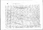
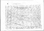
  • -Cd vs RN.JPG
    -Cd vs RN.JPG
    1.9 MB · Views: 80
  • -Cd vs RN.JPG
    -Cd vs RN.JPG
    1.9 MB · Views: 65
Hi Bill!


So the data I have seem to be all equally useless except as a broad comparison. I've seen information that says the P-47 should have much higher drag than many other fighters, but it turns out to be one of the fastest fighters of the war in the real world. Late models were good for 470+ mph and an experimental version did 504 mph. That's somewhat inconsistent with what I'd have expected if the flat-plate numbers are to be believed.
RN gives me a headache. Too long since aerodynamics. However, at sea level, high dynamic pressure, the P-51B/D is much faster (383 mph) with much less hp (1000 ?) than the P-47M/N (365 mph), which indicates the P-51 is much cleaner aerodynamically, however the P-47 engine is flat rated at 2800 hp up to 33k. The fact that it is much faster (470+, about 50 mph faster than the P-51 with only 1300 hp) at high altitude with the same hp shows the overall decrease in drag due to thinner air.
 
When I was doing RN calculations some 45 years ago, it was tough, but we DID have slide rules and first-generation calculators (with nixi tubes!). I thought I was in heaven when I got my HP45. It was WAY better than my Pickett all-metal, dual-base, log-log slide rule (still have it). Then I managed to buy an HP67 calculator (long dead) that read magnetic tapes and was sure it was the world's best. .... right ... at least it helped me through statistics. I finished the final in 7 minutes and the professor hadn't solved it yet so he KNEW I wasn't cheating using his answer sheet. But nobody had ever heard of programmable calculators until some months well after it's introduction. The Pickett still gets correct answers. The HP67 is in a land fill.

Now that Excel (or Maple) would make it easier, relatively speaking, I don't have the time to pursue long-dormant aerodynamic potential skills due to teaching new electricity courses (new to me, anyway). All that means is I know the subject, but not the new textbooks or the lab experiments. So, it takes a lot of time to stay ahead of the students. Whatever you don't know or are unfamiliar with is EXACTLY what they will ask you.

Hopefully I can get back into aerodynamic calculations in the next year or so. If not, I'm sure nobody will be disappointed.
 
Last edited:
How significant were propeller spinners in reducing drag? This would particularly apply in terms of radial engined aircraft (as many used no spinners at all, or used them in prototypes but abandoned them in production). On paper it seems like they should usually help significantly in reducing drag (avoiding excessive airflow and grad around the hub and root of cylinders where little cooling is needed, and possibly helping avoid turbulence from impacting the relatively flat and irregular surface of the engine/hub directly)

Omitting the spinner is usually not explained at all in articles I've seen on wartime aircraft development, or only very briefly cited in terms of saving weight and nothing more. (most significantly in the case of the F2A-3 -which I suspect was less to do with raw weight and more to do with helping shift CoG reawardward after the forward fuselage extension and fuel tank addition just behind the engine) For the F4F, F4U, XF5F, and P-47, the lack (or later removal) of spinner has even less explanation than the brief notes I've seen for the F2A. (and I am curious how significant something like the XP-47J's spinner would have had on a standard P-47C or D ... or M or N for that matter, without the tight cowling and cooling fan modifications)
 
RN gives me a headache. Too long since aerodynamics. However, at sea level, high dynamic pressure, the P-51B/D is much faster (383 mph) with much less hp (1000 ?) than the P-47M/N (365 mph), which indicates the P-51 is much cleaner aerodynamically, however the P-47 engine is flat rated at 2800 hp up to 33k. The fact that it is much faster (470+, about 50 mph faster than the P-51 with only 1300 hp) at high altitude with the same hp shows the overall decrease in drag due to thinner air.

Dave - the P-51B with 150 octane, wing racks only, attained 445-450 in WEP, the D about 442 so there was a difference between them and the P-47M/N it wasn't great (<20mph). The P-51H with WI (when working properly) was 472+ with racks. That said the higher HP (>2X 1650-3 and -7) and the lower drag at higher altitudes did enable the P-47 to cross over. That IS a good comparison to illustrate for High RN/low drag comparisons.
 
Dave - the P-51B with 150 octane, wing racks only, attained 445-450 in WEP, the D about 442 so there was a difference between them and the P-47M/N it wasn't great (<20mph). The P-51H with WI (when working properly) was 472+ with racks. That said the higher HP (>2X 1650-3 and -7) and the lower drag at higher altitudes did enable the P-47 to cross over. That IS a good comparison to illustrate for High RN/low drag comparisons.
But those speeds for the P-51s are for optimum altitude for the engines, about 25k. At that altitude, and at all altitudes below this, the P-47M is actually slower than the P-51s, certainly a testimony to fine aerodynamics and engines of the P-51s. But if we go up another 8k there is a different story. 33k is the max performance altitude of the P-47N turbo, which engine is still generating 2800 hp, and its top speed at this altitude is 475 mph, which it can hold to 35k. At this altitude, the P-51D at 75" has a top speed of 426 mph, or about 50 mph less using about 1000 hp, a very impressive feat. The H at 33k ft has a top speed of 440 mph, about 35 mph slower than the M, generating 1500-1600 hp, also a very impressive feat. However, above 25k, the P-47M is certainly one of the most, if not the most, powerful single engine fighter of the war with very impressive performance. Your comment about the reduced drag at higher altitudes is correct. Aerodynamically, the P-47 is benefited more by altitude than by the much cleaner P-51. Both the P-47D and cleaner P-51D has the about the same hp at 5k as they do at 20k, 2000 hp for the P-47, and 1600 hp for the P-51. However, with no change in hp, the airspeed improves by 65 mph for the P-47, but only 41 mph for the P-51 as altitude increases. Because it is so efficient at SL the P-51 has less to improve as the altitude increases.
 
How significant were propeller spinners in reducing drag? This would particularly apply in terms of radial engined aircraft (as many used no spinners at all, or used them in prototypes but abandoned them in production). On paper it seems like they should usually help significantly in reducing drag (avoiding excessive airflow and grad around the hub and root of cylinders where little cooling is needed, and possibly helping avoid turbulence from impacting the relatively flat and irregular surface of the engine/hub directly)

Omitting the spinner is usually not explained at all in articles I've seen on wartime aircraft development, or only very briefly cited in terms of saving weight and nothing more. (most significantly in the case of the F2A-3 -which I suspect was less to do with raw weight and more to do with helping shift CoG reawardward after the forward fuselage extension and fuel tank addition just behind the engine) For the F4F, F4U, XF5F, and P-47, the lack (or later removal) of spinner has even less explanation than the brief notes I've seen for the F2A. (and I am curious how significant something like the XP-47J's spinner would have had on a standard P-47C or D ... or M or N for that matter, without the tight cowling and cooling fan modifications)

When a spinner is attached and encompasses the engine/fuselage junction there is a distinct 5-10 reduction in pressure drag because without it (like a P-47 or F6F) there is a distinct stagnation region where the flow is reduced from freestream velocity to near zero.
 
When a spinner is attached and encompasses the engine/fuselage junction there is a distinct 5-10 reduction in pressure drag because without it (like a P-47 or F6F) there is a distinct stagnation region where the flow is reduced from freestream velocity to near zero.

The spinner in some aircraft, such as the Fw 190 and the Tempest II, was quite important to the correct cooling of the engine.

For some reason I think a lot of US aircraft lost the spinner between prototype and production aircraft in order to improve cooling.
 
I seem to recall that the P-47D could do 400mph at 40,000ft.

A Spitfire XIV could also do 400mph at 40,000ft, but using half the power.

The P-47's high altitude performance was due to the engine and turbo installation, with a very high critical altitude. But to achieve that required a rather massive aircraft which had a knock on effect with drag.

The XP-40J had a tighter cowl, with fan cooling for the R-2800, and the intake for the supercharger and intercooler moved back.

XP-47J2.jpg


republic-xp-47j-left.jpg


Since the turbo and intercooler were behind the pilot, I wonder if a shorter intake, perhaps with a P-51 style scoop with boundary layer separator, would have proved beneficial for drag.
 
Above 25000 ft, with ram effect counted in, the ratio between power available to P-47D and Spit 14 was 10:8, or maybe 10:9 (2000 HP vs ~1700 at 26000 ft). With exhaust thrust accounted for, propulsive power was around 1:1.
 
For a rear-mounted intercooler/air intake to be useful, you'd have to delete the belly shackle (a shame since removing that forward ducting would allow enough clearance for larger bombs and fuel tanks ... maybe even a 300 gallon P-38 tank) or adopt dual intakes to either side of the fuselage (or dual intakes below the fuselage/wings, divergent enough from the centerline to avoid turbulence from external stores).

I think the belly storage space would be a more significant gain than any potential drag improvement or weight savings. The exhaust ducting to the turbo still takes up some belly space, but it's less obtrusive than the air duct and wide enough apart to potentially allow a dip in the belly skin that a pylon could fit in between and allow relatively large cylindrical external stores (ie most bombs and drop tanks) to fit rather nicely without encroaching on the surrounding belly skin. The oil coolers would still need some droop to the cowl (or intakes rear of the cowl a la XP-47J) and would likely fit in well with that sloped belly skin as well. (bulges below the nose to either side of the engine for dual oil cooler intakes in line with the exhaust ducting, allowing a uniform blending of the lower fuselage's curves)


I'm still curious about the issue of spinners, though.
When a spinner is attached and encompasses the engine/fuselage junction there is a distinct 5-10 reduction in pressure drag because without it (like a P-47 or F6F) there is a distinct stagnation region where the flow is reduced from freestream velocity to near zero.
This explains why spinners would be a good idea, but not why so many high-performance American aircraft omitted them. (with lower speed aircraft, I could see more logic to it, especially when cost comes into play -and transports benefit both from cost and weight savings- even with some of the bombers ... I don't see the bare hub being a very good idea)
 
Last edited:
The CDo, or total parasite drag at zero lift, for virtually all WWII fighter aircraft is dominated by the wing - not the frontal area. Wetted area becomes significant in the discussion when comparing a big fighter like the Mustang to a Bf 109 but not near as much as the wing profile drag

The profile drag of the Mustang NAA 45-100 wing as well as the friction drag of the filled and primed and painted wing was simply much less than the wings of the Bf 109, P-47, Spitfire, etc.

Frontal area is important when free stream air flow is brought to a 'halt' as a stagnation point. Whatever that area of stagnation may be, it becomes flat plate drag for that relative area. That is one reason to be careful about canopy windshield design or uncowled engines.
I'm wondering if there's been too much of an emphasis put on frontal area alone in a lot of discussions on engine installations in various aircraft. The R-2600 in particular comes to mind with several topics on the P-36/40 Hawk 75/81 airframe with that engine suggesting drag increase fairly close to the frontal area difference.

As in this thread:
R-2600 table

When a spinner is attached and encompasses the engine/fuselage junction there is a distinct 5-10 reduction in pressure drag because without it (like a P-47 or F6F) there is a distinct stagnation region where the flow is reduced from freestream velocity to near zero.
This seems like a particularly big issue for reducing drag on radial engines, more so with larger diameter ones (Cyclone vs Twin Wasp powered Hawk 75s make a rather dramatic showing -and the F2A-2 and B.339 used a large spinner and streamlined cowling of somewhat higher capacity than the F2A-1/B.239).

It just seems unusual to leave that big, flat, draggy area exposed, even if rounded hub-covers and the conical reduction gear housing smoothed airflow somewhat it seems a big loss compared to having a spinner properly direct airflow and reduce drag to something more in the realm of a radiator of similar area to the remaining cowl opening.

http://www.asisbiz.com/il2/F2A-2/Br...blue-print-showing-development-history-0A.jpg
https://upload.wikimedia.org/wikipedia/commons/d/d6/Brewster_Buffalo_Mk_I,_August_1940._CH1102.jpg

In the F2A-3's case, again, it may have been a CoG issue related to the forward fuselage extension, but the removal of the spinner really looks like it would have a significant impact on drag and top speed. Likewise for the Cyclone powered Martlets and Wildcats, though they had larger fuselages and about 25% more wing area.

The Brewster cowling/spinner arrangement really does look like one of the better examples of streamlining on an American radial engined aircraft, particularly early war and particularly with the rather wide R-1820. (the R-2600 was only about an inch wider, but the greater cooling capacity required would likely mean a somewhat larger cowling to account for that)

The cowling used on the Hawk 81 P&W testbed seems particularly good for 1940 as well, but for some reason didn't use a spinner. (it almost looks like the standard Hawk 81 spinner for its V-1710-33 installation would have fit reasonably well with that streamlined cowling)
http://i34.photobucket.com/albums/d144/chrismcd3/PW_TWIN-WASP_H81A_01.png
 
Once again, the cowling on the Hawk 81 testbed looks so good for 1940 because that may be the way the plane looked in 1942.
IT didn't make the flight/s resulting in the 380mph + speeds until Sept of 1942 in any case. What it was doing or how it looked in 1940-41 I have no idea.

And again, without knowing why the spinners were added or taken away it is hard to judge. On the F2A-3 something was certainly going on. Picture of model.
Buffalo_Main.jpg

Picture of real aircraft
BrewsterF2A-3Buffalo.jpg

Brewster-Buffalo-F2A-3-hitched-to-a-tow-tractor-Ewa-May-1942-01.jpg

Please note the cuffs on the propeller blade root, usually used for extra cooling for ground running or climbing.
Buffalo went from an engine rated at 850hp max continuous to one rated at 1000hp max continuous. Counting Dutch and Belgian versions they used 4 different propellers on Buffaloes.
I have no idea if there were cooling problems in service with the F2A-2 and F2A-3s (some of which had spinners).

About 90% of the air in the area ahead of the engine winds up moving out radially out around the cowl. At speed this starts happening around where the tip of of the prop mechanism is or about the tip of a spinner is. In any case it happens well before the air hits the reduction gear box.
Because of the baffles between the cylinders and between the cylinder heads and cowl airflow through the cowl is somewhat restricted in any case (air passing 3/16ths of inch or more away from the engine does no cooling.) Closing the cowl flaps further restricts air flow and you get a high pressure area extending forward not only of the engine but actually forward of the cowling opening.
Distance of the opening from the cylinders (or forward row) and the radius of the cowling leading edge can make as much or more difference than the diameter of the actually opening. How well the Cowling blends with the fuselage is also important.
 
The F2A-2 with spinner attached also featured cuffs:
https://upload.wikimedia.org/wikipe...o_F2A-2.jpg/1280px-Brewster_Buffalo_F2A-2.jpg

http://www.afwing.com/intro/f2a/F2A-2-5.jpg

Given the position of the cuffs relative to carb and oil cooler intake, they also probably improved ram air flow through those ducts at lower speeds and higher angles of attack. (take-off and climb in particular)

Oddly, some pictures of Commonwealth Buffalos appear to be using cuffs while others do not. Perhaps not all are Buffalo Mk.Is but actually from the B.339-23 order that ended up diverted to the RAAF.

http://c8.alamy.com/comp/D8P09P/a-b...eroplane-and-armament-experimental-D8P09P.jpg (cuffed)

http://www.airpages.ru/ot/raaf_123.jpg (not cuffed, also appears to have a longer forward fuselage a la F2A-3 and thus would fit the B.339-23, which also supposedly used a rather low power engine compared to other -post B.239- models, which might explain the omission of cuffs)
Brewster 339-23
 

Users who are viewing this thread

Back