Heinkel Jet engines

Ad: This forum contains affiliate links to products on Amazon and eBay. More information in Terms and rules

OK so I took a look in my copy of "Hans Von Ohain: Elegance In Flight" and on page 263, it has a cut-away diagram of the HeS3b as part of the display reconstructions made for the Smithsonian and Deutsches Museum of Munich, and the following figures are included:

diameters
housing: 41.5 in
compressor rotor: 25.2 in
turbine rotor: 24.2 in
length: 41.25 in
speed: 11,500 rpm
thrust: 1100 lb
weight: 800 lb


and on pg 270
He S3b
thrust: 989 lbs (4400 N)
pressure ratio 2.8:1
sfc: 1.6 lb/lbf/hr
turbine inlet temp: 690C
RPM 13000
diameter 1.054 m
weight: 360 kg

he s8A
thrust: 1124 lbs (5000 N)
pressure ratio 2.7:1
sfc: 1.82 lb/lbf/hr
turbine inlet temp: 700C
RPM 13500
diameter .782 m
weight: 380 kg


(edit: Mar 7, 2022, fixed units: on closer inspection, several "mm" labels were actually "in")


No mention is made on the HeS 6, and there's no mention of it in the index either, so no info there and no confirmation on whether the drawing listed elsewhere as the HeS 6 is actually such. (the high specific fuel consumption of the HeS 8A is interesting though, and makes some sense given the poorer pressure ratio)

However, this page has some interesting info, including some of Heinkel's piston engine ducted fan developments:
Google Translate (original is spanish)


Now, with the 782 mm HeS 8a diameter figure assumed correct, and the diagrams of the HeS 8 are to scale, then the compressor rotor must be smaller than the 640 mm (25.2 in) of the HeS 3b, approximately 590 mm or 23.2 inches by my measurement. And assuming the claimed HeS 6 diagram is also accurate, and uses that same impeller, the overall diameter of that engine would be about 1170 mm or 46.1 inches. (and if the HeS 8A was directly based on the HeS 6 compressor/turbine, it's possible the HeS 6 was dismantled and cannibalized for those and some other components to be re-used in the first HeS 8 prototype; the same may have been true for the HeS 3a to 3b transition)

If the 590 kp 1300 lbf thrust figure for the HeS 6 is accurate, and 13300 rpm, then it's fair to assume the much larger diffuser and combustion chamber (proportionally larger than the HeS 3b's as well) contributed to greater compressor and combustion efficiency. (between the experimental nature of the axial diffuser, relatively short area for diffusion and expansion in the combustion chamber, and relatively small area for the flame tubes and combustion/mixing in the HeS 8 this is also not too hard to believe)

The operating RPM of various engines seems somewhat in question, though the 11500 on that one drawing of the HeS 3b may refer to its initial operating maximum, or possibly the restricted maximum for installed flight testing: this latter point would make some sense given the same sort of restrictions placed on bench vs flight thrust on other prototype engines. The Halford H.1 being a great example of many stages of increased thrust and various values being noted and spit out in different articles, confusing its performance: 1,500, 2,000, 2,100, 2,300, 2,460, and 3,000 lb thrust all being cited in different contexts, but the context isn't always given: Joe Baugher lists 2,460 lb at 9500 RPM for installed flight thrust in the XP-80, with bench thrust being 3,000 lb at 10,500 RPM, meanwhile the production Goblin I was rated for 2,700 lb at 10,000 RPM: also note thrust being about proportional to the square of the RPM, which I assume is related to the nature of centrifugal flow compressors) The drawing citing 1100 lb thrust (corresponding to the 500 kp figure sometimes cited elsewhere) being matched to the lower RPM figure and 13,000 being matched to 989 lbs in the chart also seems a bit odd, though. (there's no context given to either of those figures, so they might be mismatched or dependent on other factors)

Though if my previous assumptions are correct, and the 13000 RPM and 13300 rpm figures are also correct for the HeS 3 and HeS 6, that would further indicate improved compressor and combustion efficiency in the latter. (though if the overall pressure ratio was still 2.8:1 and turbine inlet temperatures were similar, the specific fuel consumption might not have changed much/at all, and the 'efficiency' gain would be on reduced impeller and turbine tip speeds, reduced centrifugal and creep loads, and reduced stresses on the engine components) OTOH, it may have improved fuel consumption, too as some sources claim, but I have no additional info there, just contradicting claims.


Meanwhile, an image in this thread seems to be the origins of the 930 mm (0.93 meter) diameter figure:
Motores de aviación alemanes, S.G.M.
Google Translate
Photobucket

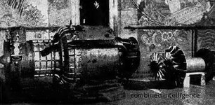
There's also a diagram of the HeS 2 and good photos of Ohain and Hann's 'garage engine' that didn't self-sustain (built prior to joining Heinkel) on that page, and the images appear to be taken from:
TURBOJET History and Development 1930-1960 Volume 1 Great Britain and Germany
Antony L. Kay
The Crowood press

I'm not sure all the photos in there are taken from that book or not, it's not totally clear, though the HeS 6 image further down seems to be a digital copy of the one from the Origins of German Jet Power site.

Oddly it also mentions:
HeS 6, on the other hand, evolution and modification of HeS 3B; it reached the thrust of 550 kp at 13,300 rpm and a weight of 420kg. The consumption compared to its predecessor was greatly improved, as well as reliability. The HeS 6 was tested under a He 111 before the end of the year. But the work stopped there, because they went to a new production model, the HeS 8, which was to propel the He 280.

The HeS 6 , was the first turbojet to receive an official name of the RLM, the 109-001 (109 is the prefix assigned to turbojets, in general, and the HeS 6 in particular was 001).

This is apparently a graph corresponding to HeS 6 ( 109-001 )


I've never seen the HeS 6 referred to as the 109-001, only the HeS 8 being referred to as receiving that designation.


Google Translate

Heinkel

Interesting info there, though I can't translate the PDF, but I can make out the technical data portions at least. (though the HeS 011's diameter seems quite large at 1080 mm, in fact that's close to the figure I got when fiddling around with scaled-up HeS 8 dimensions, based on the 782 mm diameter and assumption of a 590 mm compressor impeller, scaling up to a Halford Goblin sized 32 inch impeller)

The translated excerpt mentions the HeS 1 producing 249 kp thrust, HeS 3b producing 498 kp thrust, the HeS 6 producing 589 kp and HeS 30 producing 860 kp with a weight of 388 kg.

Google Translate info on a bunch of early other jet engine designs from around the world there, too


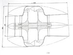
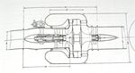
Edit: attached images of what should be a diagram of the HeS2 (at 970 mm diameter) and the mystery, possibly HeS 3 diagram listing the 930 figure.
 

Attachments

  • P1010077.jpg
    P1010077.jpg
    146.2 KB · Views: 599
  • P1010078.jpg
    P1010078.jpg
    102.9 KB · Views: 1,862
Last edited:
Kay, German Jet Engine and Gas Turbine Development 1930 - 1945 gives the diameter of the HeS 3b as 930mm with a frontal area of 0.68m².

No diameter is given for the HeS 6, but states this was a development of the 3b. The frontal area of the HeS 6 is given as 0.66m².

The HeS 3b thrust is given as 992lb @ 800km/h (497mph).
The HeS 6 thrust is given as 1,312lb @ 800km/h (497mph).
I believe that book is also where the fuel consumption figures come from that Wikipedia had cited some years ago, and Japanese Wikipedia also cites, though the latter lists it as 2.16 lb/lbf/hr for the HeS 3 and 1.6 lb/lbf/hr for the HeS 6, while the former English Wikipedia listing cited the same numbers for each, but as gallons/lb/hour, which seems obviously nonsensical as that's vastly too high if converted to weight of fuel. (additionally there's a somewhat similar error listing 1.6 lb/hp/hr in on place and lb/lbf/hr in another in "Pioneering Turbojet Developments of Dr. Hans von Ohain — From the HeS 1 to the HeS 011") I believe all figures are supposed to be lb/lbf/hr or kg/kgf/hr. (the values of the latter two would be identical as it's a ratio of thrust-force to mass or weight, so ratios that would be the same; so would N/N/hr if the engine weight was taken in newtons, though that unit is rarely used and newtons/kg usually is instead, which shifts the ratio by a factor of 9.81 due to earth's gravity making 1 kg equal to 9.81 Newtons)

ハインケル HeS 3 - Wikipedia

Google Translate


Heinkel HeS 3 - Wikipedia

But again, there's contradicting information on whether fuel consumption actually improved/changed between the HeS 3 and HeS 6, also whether some mix-ups may have been made with information specific to the HeS 3a. (with little often specified about that engine, it's plausible that data originally tied to that ended up applied to the 3b) Given the limited information on the HeS 6, the supposed drawing of it may also be incorrect and instead just another drawing of one of the HeS 3's development stages, potentially even an earlier development. (the proportionally longer combustion chamber portion ahead of the compressor appears to match the shape of some early drawings of the HeS 3 concept as well, or at least ones that appear to be the HeS 3, including the one with the 930 diameter measurement, which is presumably in mm)

The 41.5 inch diameter figure (and 1054 mm) should be accurate for the current reconstruction museum examples of the HeS 3b and appears to be what Ohain himself remembered at the time of their construction. Those reconstructions could be too large to be accurate, but then I'd think a serious question over the weight would have raised eyebrows during the reconstruction process (just as the overly-thick impeller and turbine discs/hubs were addressed: ohain explained the drawings referenced depected thicker-than necessary dimensions at the base area as they were intended to be used for an initial wooden mock-up, and reduced in thickness for the steel versions later on)

The W.1 had a larger diameter because of the arrangement of the combustion chambers, which were larger than that on the HeS 3b and HeS 6.
Based on the drawing in german that you posted, and based on the drawing and information in "Elegance in Flight" the impeller of the HeS 3b was also larger than the WU and W.1 engines (I'm not sure of the diameter int he W.2) at 25.2 inches (640 mm) vs 19 inches for Whittle's design, and both the dimensions in the drawings and the cited diameter listed in "Elegance in Flight" would support the 41.5 inch and 1.054 meter figures.

The impeller in the drawing listing a 930 (presumably mm) diameter appears to be somewhere around 480-490 mm in diameter, from what I can measure (plenty of dimensions are listed there, but not the compressor or turbine diameters, and the skew of that photograph makes precise measurements difficult: I did comparative measurements of the upper and lower radius of the compressor and total engine/casing to compare errors there).

In any case, that's close to the 19 inches Whittle used, and plausible for the overall diameter there. However, it's unclear which model of engine is being depicted. (presumably either the HeS 3a or 3b) If the 3a, then the 3b was made somewhat more compact proportionally to its larger impeller. (the difference in sizes would also at least partially explain the confusing mix of RPM figures as well ... perhaps the 3a with its smaller diameter produced around 450 kp at 13,000 rpm)

Additionally, the HeS 2 diagram with 970 mm diameter, appears to have a 669 mm diameter impeller (I'm more confident in this exact measurement, at least for what the drawing depicts) and also uses a much wider impeller mouth and relatively short/stubby tip sections with less taper than the later designs. (presumably, mass flow would be higher and compression reduced, also operating RPM would be lower with that larger impeller)

Also that 930 mm drawing and the 970 mm (apparent HeS 2) one appear to be possibly drawn by different people, as the former crosses its 7s while the latter does not. (both have exaggerated tips drawn on their 1s, though, but no base serifs)


Also, the german-language drawing posted with the 640 mm diameter impeller also lists 11,000 RPM and 450 kp compared to the 11,500 rpm and 1100 lbf listed in the otherwise similar drawing in "Elegance in Flight." Additionally, wikipedia's current reference lists 11,600 RPM and 1100 lbf, which matches up even better with thrust being proportional to the RPM squared. (ie increasing from approximately 450 to 500 kp) However, if the HeS 6 was literally a modification of the HeS 3b, with similar diameter/impeller dimensions, it producing 550 kp (or even 590 kp, or slightly more) at 13,300 RPM would seem a bit low, unless performance increase dropped off at certain high RPM ranges (perhaps supersonic losses due to higher mach numbers at the impeller tips?) and being heavier possibly due to using a more heavily built impeller and turbine to tolerate higher rotational speeds.

The air would also be heated by the time it reaches the blade tips, raising the speed of sound somewhat, but still, it would probably be supersonic at 11,500 rpm and possibly not at 11,000 RPM as the air would need to be only just over 61 C to have a speed of sound of 368.6 m/s with the tip speed just about exactly that, and at 11,500 rmp at 385 m/s it'd need to be 89 C to stay below mach 1, and 11,600 would be 389 m/s and 95C, but at 13,300 rpm it'd be up to 445.7 m/s, requiring a temperature of 188 C to be subsonic, which seems unlikely. (albeit once it does hit supersonic, you'd have supersonic heating to consider as well)

OTOH, the proportion of the impeller in the supersonic range would also be a factor, and initial transition with supersonic speed at the tip might not change behavior much, but as it progresses, the change is more prevalent and the RPM squared proportion of thrust is no longer valid. (it also might not be to due with efficiency losses at supersonic speeds, at least not mechanical efficiency, but may be just physics of supersonic flow changing fluid behavior and changing the thrust curve involved: so may not translate to inefficient power consumption at the turbine or specific fuel consumption, or poorer pressure increases) Also noteworthy is that the Halford H1 Goblin should be operating with a subsonic impeller or just slightly transonic up to about 9,000 RPM, or perhaps even 9,500 RPM if the air temperature reaches 100 C at the tips.

Also note that the much higher temperature of gases at the turbine mean the tip speeds there are well under the sonic limit. (by 600 C, the speed of sound is 697.4 m/s, vastly lower than tip speeds experienced in these engines, and moreso for the axial turbine of the whittle and Halford engines, with much lower diameter than the compressor impellers)

OTOH, the Goblin seems to have continued pretty much proportional (square of RPM) thrust values from 9500-10500 RPM (with 3000 lbf at the latter speed with the original prototype H.1 and Goblin 1 engines, though I don't think they were ever cleared for flight at that power level), but other factors might be in play with Ohain's engine, or again, the 13,300 rpm figure isn't valid at all.

Also, an engine of the Goblin's configuration should be around 39 inches or 990 mm in diameter if directly scaled down to a 640 mm impeller, though it's possible a more compact arrangement would be also possible, I don't see that being the case with the HeS 3's folded/reverse-flow configuration. (diameter at the edge of the radial diffuser alone might be smaller, or even the slightly larger diameter at the split airflow outlet portion, which appears to be about 850 mm in the HeS 3b drawing with the 640 mm impeller. The use of an annular combustion chamber and continuous annular diffuser outlet might also improve things slightly over the Goblin (and Ghost) with individual flame can diffuser outlets. (the Turbomeca Marboré might be more comparable in compactness, though also a decade later's worth of research to build on: also interesting to note it used a fairly simple, straight-blided centrifugal impeller with a separate inducer segment added on top of it, also similar to the J44, though not a mixed-flow arrangement, still probably allowing a simple aluminum alloy casting for the main impeller body and a cast or forged and less elaborately milled/finished inducer blade extension section mated to it; the configuration is also simpler/cheaper than Ohain's axial inducer fan with its airfoil shaped blades, though doesn't serve entirely the same purpose as Ohain was also aiming at addressing intake losses and surging issues) The Marboré engine also seems conceptually closer to what Ohain might have developed had he switched to an axial turbine for the HeS 8. (for the same weight and length of engine, there'd also be a broader set of options for improving diffuser and combustion chamber airflow with an axial turbine, plus once partnered with Hirth's engineers, their existing developments of axial turbines mated to centrifugal compressors in their own turbocharger developments could contribute to Ohain's works ... as could the HeS 30 project's work, though while Muller was leading it, I suspect there might have been communication and collaboration issues of various sorts, plus progress on that engine itself was slow until part way into 1942, while the Hirth connection would have been established shortly after the He 280's first flight and improvements to both the centrifugal compressor and experiments with axial turbines based on Hirth's experience could have started soon after, but apparently didn't)

Likewise, the Jumo (not Junkers Aircraft) and BMW gas turbine developments were partially based on earlier and parallel turbocharger developments, especially with BMW's air-cooled axial turbine centrifugal compressor turbocharger used as the basis for a 2-stage centrifugal P.3303 engine, which was later dropped from development to focus on the P.3302 (003) and overly-complex P.3304 which was later abandoned. (the P.3303 might have been wise to keep in parallel development with the P.3302, though, particularly if development shifted to using common combustion chamber and turbine developments, given the axial turbine was less experimental than the axial compressor and efficient centrifugal compressor design was better understood and continually advancing due to supercharger design work)

Jumo had the turbocharger work applied to the 2-stroke opposed piston diesel engines, with work on the 205 and production in variants of the 207, and use of air-cooled hollow turbine blades. Though possibly using machined/bored vent holes rather than drawn (or folded and welded) blades as in the 004B-4 implementation. Small, round holes are present in the turbine:
File:Jumo 207 im Technikmuseum Hugo Junkers Dessau 2010-08-06 01.jpg - Wikipedia

The turbine there also appears to be of the impulse type (where the stators/guide vains direct gases to impact the blades like a water wheel or radial inflow turbine, like buckets, hence also why turbine blades are sometimes referred to as buckets). Impulse bladed turbines were more common and well understood, but used along with reaction bladed in steam turbine and turbocharger applications. (there was another thread that had pictures of a multi-stage steam turbine section of a large ship's engine with a mixture of reaction and larger number of impulse turbine blades present) I believe impulse blades aren't less efficient in terms of mechanical efficiency yields, but can harness less power per stage (and given turbine/blade size) than reaction blades, but are both somewhat simpler and less heavily stressed in operation. (being a simpler, basically symmetrical airfoil shape, the simple round hole bored into the center of the blade would be more effective at cooling than a similar attempt made to a reaction turbine: plus machining such without a high failure rate might be difficult for the latter) An engine of the 004's size might have needed a 2-stage impulse turbine for those reasons, but may have been more reliable and had a longer turbine life. (given how conservative the 004's general design was, I'm a bit surprised at that decision, particularly with the prototypes using solid blades of special high-temperature molybdenum-cobalt alloys that would not be used for mass production, where the diesel turbines were production commodities; then again I'm also somewhat surprised that an even more conservative, centrifugal compressor gas turbine engine wasn't in parallel development as a fallback or also potentially as a complementary development: diameter would be larger, but weight would be lower and well suited to being embedded in single-engine fuselage/boom configurations, plus the larger diameter would also be less problematic for turboprop or geared-turbofan developments of the same basic design, while the lower weight and length would be significant advantages)

Also, diesel engine exhaust tends to have a lower temperature than gasoline engines, so the turbochargers of the Jumo 207 weren't as thermally stressed as that of BMW's or Hirth's (I'm not sure, but I believe Hirth's turbocharger also used air-cooled blades, and thin, drawn or folded hollow blades were used in the 011's turbines)

Jumo did choose impulse blading for the 004 (and 003) compressor section and this was due in part to the much cheaper manufacturing methods with the blade shapes simple enough to allow stamped aluminum and steel blades to be used.

The use of reaction blades in the HeS 30 was also one of the main reasons for the RLM being concerned about its design. Precision machining was required for that and not ideal for war-time conditions (with high speed steel shortages especially, and turbine engines already consuming nickel and/or chomium in various components ... plus the majority of high performance piston engines using chrome and/or nickel alloy steels in cylinder liners and a few other areas, and spark plug electrodes also usually needed nickel). Though given the 5-stage compressor and smaller overall size of the HeS 30, the material consumed shouldn't have been that great, and it may have been the skilled labor man-hours involved that concerned them more. (particularly as skilled craftsmen were not exempt from conscription into combat duty)
 
The HeS 8 was the first jet engine to receive a type number - 109-001, or He 001.

It achieved 1,323lb static thrust, which was less than the 1,544lb thrust @ 800km/h (497mph) which was planned. This must put doubt on the thrust numbers above.
Most sources I've seen list the HeS 8 as being designed for a 700 kp thrust, but delivering an initial 500 kp by the time it was used for the He 280's first powered flight (and then rushed with fuel leaks still present in order to meet Udet's deadline), and increased to 550 kp later in 1941, but supposedly only reached 600 kp after an additional axial compressor stage was added behind the centrifugal one starting with the HeS 8 V15 and improved ducting or diffuser arrangement for the centrifugal stage used in the V16. (most sources claim it never exceeded 600 kp, that is if they cite its peak performance at all)

What seems to be consistently cited was the HeS 8's compressor and combustion chamber arrangement were considerably more difficult to get working than initially assumed, and it took nearly two full years after the HeS 3 successfully flew before it was capable of powering the He 280. (so the poorer performance than the previous designs seems plausible given the unexpected problems manifesting with the HeS 3, including the poorer compression ratio of 2.7:1 typically cited)


Note that von Ohain only built a centrifugal flow turbojet as an experimental proof of concept (to show that a turbojet could produce thrust). His intention was to move to axial flow designs, but that was blocked, to a degree, buy the RLM. The RLM, in fact, insisted on the diagonal compressor in later Heinkel turbojets. HAd they went with a centrifugal compressor behind teh axial compressor, they may have been more successful.
He did it as both a proof of concept and a short-term expedient. Also remember, he did his early work without knowing if/when war would break out and also not with the concern on military applications, but more his (and Heinkel's) personal passion and ambition, but just after the He 178's first flight, you had the invasion of Poland and the beginning of WWII, thus the game changing (also a partial explanation for the RLM officials' modest interest at that flight, partially due to their preoccupation with the invasion plans).

Ohain apparently wasn't planning on continuing any of his own developments directly, with Heinkel mostly interested in Wagner/Muller's former-Junkers team and their work on the HeS 30 (once that design was selected from a variety of more complex and less immediately viable options), but Muller apparently misled or misscommunicated (or underestimated) the time it would take to move to Heinkel and start-up developments there, and it took some months before it was clear the HeS 30 would not be flight ready by early 1941 and a substitute (with close-enough dimensions and power to fit the already-in-development He 280) was required, and Ohain quickly put together the basic design of the HeS 8.

However, with the problems with the HeS 8's design changes over the earlier engines presenting fairly early on, it seems they had fair warning to consider dusting off the HeS 3 (and 6) as stand-ins and have an alternate wing built with modified outer spar section to allow the engine to be mid-mounted (or partially raised) but otherwise leave the airframe unchanged. (and also intend the simpler, straight-spar wing for more economical mass production later on, though I'd assume switching to a simpler, tapered wing planform like the He 100 would further reduce costs over the elliptical one)

Additionally, with problems with the axial diffuser presenting, Ohain also could've changed tactics and returned to a radial diffuser, but still dropped the folded, reverse-flow combustion section to keep diameter down and could have considered switching to an axial turbine (though the radial one would be the short-term solution). He also could have considered a 2-stage centrifugal configuration with reduced impeller diameters, but then that would also contradict the ease of working with 1 centrifugal impeller and a matched radial turbine. (though calculations required for a 2-stage centrifugal arrangement may still have been easier to do with a radial turbine than one or more axial ones, but a larger diameter radial turbine might also be required, again becoming a factor in minimum overall diameter, though still giving more options for a large combustion chamber section, and increasing the number of turbine blades might avoid any increase in diameter required) Then again, if the axial diffuser was used only between the 2 stages, and the second stage was followed by a larger, more efficient (and better understood) radial diffuser followed by guide vanes further diffusing the air and guiding it into the combustion chamber, and splitting it into the flame-tube section and the bypass section(s). That way, even a radial turbine of significantly larger diameter than the compressors shouldn't contribute to maximum diameter. (and a large radial guide vane section shouldn't be required for the radial turbine inlet, or rather, it should be proportionally smaller than the diffuser requirements as the velocity-to-pressure transition mechanics aren't needs, just proper direction of the gas flow to impact the turbine blades)

Also, the axial diffuser of the HeS 8 may have had problems, but it did make multi-stage centrifugal configurations a good deal simpler than the normal radial diffuser arrangement, and efficiency losses in the second stage inlet should be less, partially offsetting the problems with the axial diffuser itself. (also, higher pressure ratios should be possible at lower operating RPM, so lesser centrifugal stresses on the impellers and turbine and better specific fuel consumption for a given turbine temperature)

Also, the Radial inflow turbine Ohain used in the HeS 3 and HeS 8 designs only used nickel steel (a Krupp alloy, probably Chromadur or similar) in the turbine blades themselves, while normal steel (typical manganese steel, probably in the low-carbon range due to both the lower cost/easier machining and better high temperature stability) was used to the turbine disc and hub, and the disc was cooled with bleed air passed between the compressor and turbine discs. (the compressor used similar steel for its disc, with aluminum sheet metal blades attached to it)

Based on the technical drawings in "Elegance in Flight"
pg 267 depicts knob type blade retention (de Laval bases), similar to those which failed the Whittle WU turbine and were replaced with the "fir tree" type of dove-tail. (both the turbine and compressor blades were retained this way)
https://www.princeton.edu/ssp/trips/data/whittle.pdf
Early experimental turbine blade from a Whittle jet engine

Turbine blade retention issues were noted to be among concerns with Ohain's radial turbine, but change in the retention method similar to Whittle's developments may have similarly addressed the problems and allowed increases in RPM.

There were also problems with fatigue failures near the turbine blade tips, but air cooling may have solved that as well (though an engine using 2-stage centrifugal compressors at lower RPM also may have helped). And with the turbine disc already air-cooled and working well enough with plain steel, the pressed, sheet-metal nickel-steel blades could be cooled with air cooling slots cut into the turbine disc and/or central hub walls, with an increased flow of bleed air used to force air out through the turbine disc and past the blades. (given stresses were greatest near the blade tips, slots or holes/jets cut in the disc itself seem more useful than the root/hub section, plus would avoid having air channels running near the rear turbine bearing and complicating that) This would also avoid more costly routes like use of thicker nickel steel sheet metal for the blades and keep weight down. (and such cooling slots would likely work far better with a radial turbine than similar systems did with slots cut into the axial turbine disc in the early 004B models with solid turbine blades that had cooling air ejected between them from the disc, as much of that air would get blown away by hot exhaust gases and not be able to stick/flow down to the blade tips, but with the radial turbine and cooling vents along the length of the blade edges, air should be much better distributed, plus vent holes could be cut larger/more numerously near the blade tips if desired, where the axial design could try to do that by having cooling air jets running the perimeter of the exhaust nozzle or possibly built into the inlet guide vanes, but Jumo doesn't seem to have implemented this)

Plus, the simple, pressed/stamped sheet metal construction of Ohain's turbine blades would make efficient use of strategic materials and reduce skilled labor costs. (much of the sheet metal portions of the engine could be formed on guides/dies, while a few cast and machined parts like the casings, hubs, and discs would take some milling operations) They also probably could have switched from the steel-and-aluminum compressor to a cast aluminum or magnesium (elektron) alloy impeller of greater strength and lower weight. (and use a separate set of inducer blade tips to form the inlet portion of the impeller, but possibly still require the forged/stamped aluminum axial inducer stage as well for its original purpose unless other improvements to the compressor or intake were made: using a bifuricated intake as on the Goblin or a series of inlet guide vanes might have been alternative solutions, possibly variable-pitch inlet guide vanes like Jumo's swirl-throttle developments on the Jumo 213 supercharger, though that might be no simpler than the rotating, but fixed pitch inducer Ohain already used)


Also another thought: I considered the He 100 for possible jet engine conversion in a stepped layout (like the Yak 15) with the turbojet exhaust under the fuselage, but realized the He 100's lower tail position and (especially) close wheel wells of the main gear would make that more difficult without further modification, and while re-using some He 100 components for a production aircraft might be appealing (it was already supposed to be optimized for reduced cost/man-hours for manufacture and some tooling had been invested already, at least enough for the small scale series production of the D-0 preproduction model), but not so appealing for testbed purposes or conversion for experimentation in general.

However, the wing and landing gear configuration of the He 112 seems far more suitable with a good deal of clearance below the fuselage and outward-retracing gear even further away from that. The weight of the prototypes also seems within the useful range for engines in the weight and thrust range of the HeS 3, 6, and 8 to be tested in. There were also more numerous He 112 prototypes and preproduction series airframes to choose from for conversion and characteristics were similar enough to the He 100 to be a valid test for feasibility in a single-engine tractor-jet variant of the He 100 airframe.

Also, melting of the tail wheel rubber was a problem on the Yak 15 (they addressed with a solid metal wheel), but a split/divergent bifuricated exhaust arrangement with a sufficient gap between to avoid excessive jet blast against both the tail/fuselage and tailwheel would seem a good solution. (straight exhaust results in less lost thrust, but as does minimal exhaust pipe length, so losses would still likely be much lower than the He 178, and the lack of intake losses on top of that)

They also could've experimented with thrust augmentation ducting, using an airfoil shaped cowl/venturi arrangement to draw in additional air around the exhaust, resulting in a larger volume of slower, cooler air being exhausted, more thrust (at least at lower speeds and take-off) and less heat damage concerns, including to melting asphalt on runways. (there had been various investiagtions of such augmentation for jet thrust of various sorts, including ducted fans and rockets, in the early 20th century, though a particularly useful one from 1932 published by the NACA is very relevant, and there were some other publications and magazines that summarized portions of the findings from that report, similar to the popular mechanics/science type publications that also featured Whittle's patent drawing and some details following his 1930 application).

NASA Technical Reports Server (NTRS) - Tests on Thrust Augmenters for Jet Propulsion

It tests a Melot type nested-augmentor as well as a single venturi style arrangement using a single stage augmentor of a similar airfoil shape to the melot ones. (it appears to use the same duct/airfoil as the final stage of the Melot arrangement) Note the jet pressures are in psig, not absolute pressure. (absolute pressure would be 14.7 psi greater)

Also a longer report/study from 1933 NASA Technical Reports Server (NTRS) - Jet Propulsion with Special Reference to Thrust Augmenters

Single-stage thrust augmentation ducts are fairly typical additions to pulsejet engines used by modern hobbyists, too, and tend to boost thrust by 50 to 80% in that application. (though the drag from a simple, fixed augmentor duct makes this gain less and less at higher speeds, it's quite useful at most speed ranges used by model aircraft and jet-powered gocarts and the like; albeit part of that drag is related to the low critical mach numbers of short, simple augmentor ducts, and longer, more streamlined ones or the similar shrouded duct designs that cover a portion of the exhaust pipe, or even the entire engine, would be better suited to higher speeds: the US experimented with shrouded pulse jets post-war and improved both thrust and SFC that way)


Edit, this is neat:

Wayback Machine

Apparently, the original design for an enlarged (4000-4400 lbf class at the time) Goblin derivative was 57 inches in diameter, but this was deemed excessive, and it was redesigned with a narrower radial diffuser feeding into cascade diffuser vanes which transitioned from radial to axial flow on their way to the outlet ducts. Pairs of outlets were chosen over single ones as a smaller number of larger combustion cans were used with greater overall volume for better combustion efficiency, but 2 inlet ducts were used for each chamber to avoid the need to design slitter guide vanes into the diffuser section. That brought the diameter down to 53 inches, smaller than 93% of the original.

However, from the cut-away reproductions of the HeS 3b, and the drawings I've seen, it looks like Ohain had already implemeted a form of cascade or mixed-flow diffusers in his reverse-flow section, but the overall diameter was then increased by the flame tubes/jets being located outside of the diffuser ring perimeter rather than behind it, so had the existing diffuser arrangement been retained, but folded entirely the other direction, to fit between the compressor and turbine, it should have been similarly compact to the Ghost, though likely much less refined in actual implementation of the compressor impeller, diffuser, combustion chamber, turbine and general aerodynamic shaping and such, but had plenty of room for further refinment toward that end) Keeping the combustion chamber design as similar as possible to the HeS 3b and 6 (successful configurations) and using similar length and volume of overall airflow passages in the diffuser and combustion chamber would seem to have been a safer, sensible engineering choice. (diameter less than an inch greater than the HeS 8 seems feasible with such a scheme too, but the area between compressor and turbine discs probably needed to be at least 50% greater, perhaps close to double; this would increase weight over the HeS 8 a good deal due to the longer, heavier shaft and longer/larger combustion chamber, but should improve thrust, specific fuel consumption, and general reliability, plus the combustion would be kept far enough away from the compressor disc to need any bleed air to cool it, and a smaller bleed chamber could be made for the hot section of the engine to keep the inside walls of the combustion chamber and the turbine disc cooled, as well as to supply compressed air for any cooling ports or slots cut for the turbine blades)
 
Last edited:
Has anyone found the von Ohain Patent. It was supposed to be taken out after Whittles. One source I located Ohain could not get the patent because of the existence of Whittle's design. There is no joint patent with Heinkel before the war. So what's von Ohain's story?
 
I remember seeing an actual Heinkel jet engine in Deutsches Museum (science museum) of Munich around 15 years ago. I'm half sure it was a 08. The sign stated it produced around 600Kg of thrust. Does anybody have actual images of it, because I cannot find one through Google images and I'm starting to believe I'm imagining things... :crazy:
 
I remember seeing an actual Heinkel jet engine in Deutsches Museum (science museum) of Munich around 15 years ago. I'm half sure it was a 08. The sign stated it produced around 600Kg of thrust. Does anybody have actual images of it, because I cannot find one through Google images and I'm starting to believe I'm imagining things... :crazy:
Welcome to my world.
 
I remember seeing an actual Heinkel jet engine in Deutsches Museum (science museum) of Munich around 15 years ago. I'm half sure it was a 08. The sign stated it produced around 600Kg of thrust. Does anybody have actual images of it, because I cannot find one through Google images and I'm starting to believe I'm imagining things... :crazy:
Here is the Heinkel HE-S8a. The report states it was never flown in an airframe but mader some flights in a conventional aeroplane as a test bed.
 

Attachments

  • heinkel hirth 08.jpg
    heinkel hirth 08.jpg
    31.9 KB · Views: 97
Here is the Heinkel HE-S8a. The report states it was never flown in an airframe but mader some flights in a conventional aeroplane as a test bed.
Thanks for the pic. Hard to say if it was that, since it was cut in half. I've been in so many museums over the years that my memories of it are quite blurred. I was sure it was in the Deutsches Museum and that it was an Heinkel, not the more common Jumo or BMW.
 
Hmm, also I'm now suspecting the 36.6 (0.93 meter) diameter of the HeS 3b is incorrect, both by comparing the dimensions of the HeS 8 (assuming the compressor and turbine are of similar diameter in both) and more definitively, to the drawing of the HeS 3b that cites a 640 mm diameter 'laufrad' (which appears to refer to the turbine wheel). And taking some measurements of that drawing, it appears the overall diameter should be approximately 1090 mm and not 930.

It's quite possible that 1093 mm is the true figure, and that's where the 93 comes from, as an error.

The "Pioneering Turbojet Developments of Dr. Hans von Ohain — From the HeS 1 to the HeS 011" article doesn't expressly mention diameters either, but frontal areas instead with .68 m^2 and 7.31 square feet given for the HeS 3b (and the diameter can be derived from that by assuming the engine is a perfect circle and using pi*r^2 giving 36.61 inches for the diameter if the more precise 7.31 figure is used). So I suspect the areas were calculated erroneously for the HeS 3 at least, possibly by inputting .930 meters (or perhaps .9301) instead of 1.093 meters at some point and deriving the rest of the errors from there.

I'm also going to assume the HeS 8 frontal area figure of 5.05 square feet is accurate as it matches other citations of approximately 30.5 inches diameter and matches drawings of the HeS 3 or HeS 6 shown to scale with the HeS 8. Though the 5.05 sq ft figure works out to more precisely 30.43 inches, which would round down to 30.4 and not 30.5, so I'm not sure about that. (the less precise .47 square meter figure works out to about 773.58 mm or 30.46 inches, and rounding applied in any number of stages of that would make it even closer to 30.5 inches, particularly if you treat it as .470 square meters with 3 significant figures, then round to 774 mm and end up with 30.47 inches)

The 1.093 meter (43.0 inch) figure is also very close to the same diameter as Whittle's W.1 and W.2 engines, or Derwent or GE developments of the W.1 and W.2 all in the 41.5 to 44 inch range, with the W.1 prototypes cited as 43 inches), but the W.1 used only a 19 inch impeller to the 640 mm (25.2 inch) diameter impeller of the HeS 3b, though the Whittle engine used a double-sided impeller with surface area similar to that of a single-sided 26.9 inch diameter impeller (though the comparison is more complex than that as there's blade length/chord among other issues to consider, plus Whittle's configurations required sufficiently wide space between and around the compressor outlets and combustion chambers to allow intake to the rear side of the compressor). The Halford H.1 Goblin engine by comparison had an overall diameter of approximately 50 inches and impeller of approximately 32 inches diameter. The tip-speed of the HeS 3 at 13,000 RPM would also be fairly similar to the desired maximum operating RPM that Whittle had targeted for the W.1 of 17,750 RPM. (13,000 of the HeS 3b impeller would approximate 17,240 RPM for a 19 inch impeller and the HeS 6's 13,300 would be 17,640, and HeS 8's 13,500 is 17,900 RPM ) However, the W.1 struggled to reach the desired RPM while Ohain's designs apparently ran at full speed by 1939)

The HeS 8, whatever its difficulties were with combustion and its axial defuser, did manage an impressively small diameter relative to its compressor and should have been quite appealing to scale up further, though likely with a switch to an axial turbine and possibly flame cans rather than an annular combustion chamber. Also, had it been made just slightly larger, similar to the 32 inches of the Jumo 004, it probably would've managed to approach the 700 kgf design thrust originally intended. (though the combustion chamber really needed to be longer by the looks of it, and while it would've increased weight and stresses on the rotor shaft, it should have kept the cold section cooler on top of better combustion and homogeneous mixing of the gases past the flame tubes fewer hot spots to develop in the turbine section, plus a greater overall length would generally mean shorter intake and exhaust channels, and fewer losses there, even in nacelles: one of the downsides of both Ohain's earlier and Whittle's reverse-flow/folded arrangement as well)

However, given the trouble and delay in actually getting the HeS 8 working at all, but given the fact the HeS 30's smaller dimensions had already been included for the design specifications of the He 280 (and considerably design work done and construction had already begun), with 43 inch diameter engines, it seems like the best option would have been building an alternate, substitute wing that allowed mid-mounting of the engines, or at least partial submersion in the wing, probably requiring a curved spar, but perhaps not as dramatic as Gloster's fully mid-wing mounting, perhaps one that allowed some 10 inches of the engine's upper half to be submerged in the wing, leaving most of it still below. (closer to the late 1940s Sukhoi Su-11 with its Lyulka TR-1 engine installation)

Additionally, scaling up the existing HeS 6 to something closer to the Halford Goblin engines, suitable for a single-engine aircraft, would be much more reasonable for a large-diameter engine. (the twin-boom arrangement also seems to be appealing in general for short exhaust and ease of engine access or replacement) Though with the radial turbine consuming more stainless steel, a transition to an axial turbine seems likely prior to mass production, either with flame cans or an annular combustion chamber. (again, the turbine and combustion chamber developments of the HeS 30 should have been applied to centrifugal engine developments as well) Meanwhile, the HeS 6 itself might have been a good interim engine to refine as-is for production, at least in the short-term. (and probably more valuable on high speed recon aircraft or bombers than fighters in the early-war period, or as booster engines on those same types, and again also potentially working well alongside Junkers two-stroke diesel engines)

Hmm, for that matter, installing booster engines on the He 177 prototypes and using two, conventional, but less powerful main engines (like BMW 801 or DB 603) along with a number of booster jets for take-off assist and combat speed boost might have allowed for a more practical design than the coupled engine arrangement and heavier, taller landing gear to complement the larger propellers. (though I suppose a push-pull arrangement of smaller engines also would have avoided some of those same problems and allowed use of the more plentiful Jumo 211, but that would seriously alter the center of gravity with engine weight added to the trailing edges of the wings)

OTOH, jet engines would be more problematic for night operations with the exhaust plume rather visible, at least when throttled up. (if only used for take-off and escape/evasion that would be less problematic, and the cruise and bombing operations could be done with the turbine engines at idle, though they likely couldn't be shut down and re-started in flight, or at least not re-started if allowed to cool below operating temperature of the vaporizing burners; re-lighting a flame-out might be possible if action is taken quickly enough, but cold starts would be another matter)


Additionally, it seems Ohain chose the radial inflow turbine for the additional reason of easily matching it to a centrifugal compressor with fluid dynamic and other physics and engineering calculations of properly matching impeller and turbine being much simpler than if one or both was of an axial design.


Edit: apparently Laufrad actually refers to compressor impeller Laufrad (Strömungsmaschine) – Wikipedia based on that at least. And given the compressor is slightly larger in diameter in that drawing, the overall diameter appears closer to 1059 to 1060 mm meters and not 1093, which would be 41.7 inches. (and that wouldn't fit with my typo hypothesis, though I suppose it's possible the HeS 6 was slightly larger at 1093 mm or the error came from somewhere else entirely) The HeS 6 being a slightly greater diameter as well as longer and heavier would certainly have made it even more of a poor fit in the He 178, which was noted for being unable to mount it properly. (information is confusing, but it sounds like the V2 prototype with retractable landing gear was to mount the HeS 6, but never flew, either related to those problems, or due to other issues with malfunctioning landing gear)

The long, curved intake manifold of the He 178 also seems ill suited to such engines, even more so as mass flow increases. (shorter, fuselage mounted side intakes close to the engine's location seem like they'd have worked out much better, probably below and behind the wing) The lack of nose intake also would've made a shift to tricycle landing gear more practical, and the tail arrangement could have been switched to a single-boom, allowing a much shorter jet exhaust pipe to be used. (had there been a V3 prototype built for more extensive testing of jet engines, I imagine that might have been the arrangement, that or a nose intake that split around the sides of the fuselage more like the Gloster G.40 or perhaps the Me P.1101)
I have completed considerable research into von Ohain through patents. I have not found a single jet patent in his name before 1939. There is no reference to him in the T Force reports by the Allies after WW2 except to say that he worked as an engineer at Heinkel. The only drawing I have seen of a Heinkel compressor is a joint patent with Heinkel and Max Hahn. It would seem that everything that has been said about him before 1960 is pure conjecture in the field of gas turbine research. Where are his patents they talk about?
 
I remember seeing an actual Heinkel jet engine in Deutsches Museum (science museum) of Munich around 15 years ago. I'm half sure it was a 08. The sign stated it produced around 600Kg of thrust. Does anybody have actual images of it, because I cannot find one through Google images and I'm starting to believe I'm imagining things... :crazy:
You mean you also see Heinkel jet engines lying around in museums? :lol: No, seriously... I remember it was cut in half to show the inner workings. It wasn't the 03 or the 01 but it looked a lot like the HeS-11 with mixed axial and centrifugal compressors

EDIT: could it have been the 109-006 (HeS-30) ?

Some of the later variants of the HeS 8 added a single axial stage behind the centrifugal stage and should indeed have somewhat resembled the HeS 11 to some extent, but smaller, with a conventional centrifugal compressor (not diagonal) with a smaller axial "inducer" fan stage ahead of it at the intake, and only a single axial compressor rather than the 3 of the 011. The unusual radial flow turbine similar to the HeS 3 should also have been present.

The 600 kg thrust would also be consistent with the late variations of the HeS 8. That appears to be the thrust reached before development on the design halted. Wikipedia lists the added axial compressor stage being added from the fifteenth prototype onward (V15) and while I recall some mention of this elsewhere, I'm unsure of the source of this info.

I've never seen any pictures of an HeS 8 museum example, be it intact or cut-away, but that would be really neat. (likely a reproduction cut-away similar to the HeS 3b since I don't believe any of the originals survive)
 
I also stumbled on this further development of the HeS 011 as well as a much larger and more advanced axial turbojet design developed for Spanish and Egyptian contracts in the early 1950s.

Paneles de la Exposicion. Carlos Sanchez Tarifa. Pionero de la propulsion aeroespacial en España. Universidad Politecnica de Madrid


Apparently that HeS 011 derivative weighed 600kg and produced 1600kg of thrust.


According to that site, and the warthunder forum post the HeS 053 was a 9000 kg thrust class engine. (prototypes sent to Egypt were producing 6500 kg thrust)


I would assume that Heinkel CASA 101 design was competing with the Messerschmitt design that also got Egyptian interest and got further developed into the HA-300 in the 1960s.
 

Users who are viewing this thread

Back