Help needed - Hamilton Standard blade face template dimensions

Ad: This forum contains affiliate links to products on Amazon and eBay. More information in Terms and rules

karoisan

Recruit
9
10
May 22, 2022
Hi there,

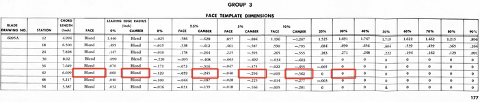
I need help in the interpretation of a Hamilton Standard propeller blade face template dimensions. See attachment.
  • What does "Blend" mean?
  • How to interpret "Camber" values? Do they refer to the camber side or to the cumber line of the profile at a given station?
  • And how to deal with zero cumber values?

Thanks
 

Attachments

  • 6095A face template dimensions.png
    6095A face template dimensions.png
    192.2 KB · Views: 23
You asked about "Blend", that is just how the radius is profiled to the rest of the blade. I have looked at all of the other blades and the only blade that is not blended is the model 6813 blade at the inboard stations. I have worked on those blades, for a DC4M, and they are definitely not blended, but they are shot peened in the area.
 
Thanks Michael!
By the way, is there any public information on what type of airfoils are used on vintage HS blades, or is that still an industry secret? Based on the template data for the 6095A blade I posted, it appears to use Clark-Y outward from station 30, due to the 0 values. The rest is unknown to me.
 
Sorry I do not have any idea on the airfoil type. That typically is kept by the manufacturer. I do not know of any public information on the airfoil type.
Inboard from 30 inch station is where the blade transitions from the round shank to the airfoil shape. The inboard portion of the blade may be designed to aid in engine cooling.
 
They are %ages of max h. Thus the 0.3 station has an ordinate value is 0.998.
Look at Figure 3 of NACA TN 378 to get the h/b value for the r/R locations for the R.A.F. No. 6 modified.
 

Users who are viewing this thread

Back