Military Kev
Recruit
- 5
- Dec 5, 2020
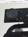
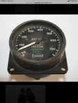
I'm new to this site and am hoping that someone could help me. I'm looking at finding a Dunlop (Eureka) 1-750lbs air pressure gauge. I can't find anything on the web about this gauge. It was mounted on the upper left Horsa instrument panel. I found two pictures of one that had I think a Dunlop number of AHO 15x51, and a RAF part number of G6A/3347. Does anyone know what the complete AHO number is? Thanks for any help
")

.JPG")
.JPG")