Klimov VK-107 - help needed (1 Viewer)

Ad: This forum contains affiliate links to products on Amazon and eBay. More information in Terms and rules

Piper106

Airman 1st Class
193
29
Nov 20, 2008
Anyone have any data, images or links they can share regarding the Klimov VK-107 engine. Cross section drawings would be great.

What little i have read about this engine is conflicting or how shall we say... confused.
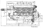
I have only seen one image, and that is a front quarter view that does not show many important parts of this engine. .

This engine gets briefly discussed on this forum in an earlier thread about M-105 power outputs / ratings.
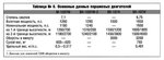
Best I could make out from the table in that thread, it looks like the often quoted 1650 PS / HP output came required running at 3200 rpm.
That high of an rpm seems quite daring, at least based on what I think I know about lack of quality if not outright shoddy construction during that era in the Soviet Union.
 
Last edited:
First, thanks to Aurum for originally posting the information below.
Can anyone translate the attached row captions??
l_~1.GIF
 
Last edited:
looks like power ratings
My guess

Compression Ratio = 6.75
Mass = 765 kg
Takeoff power = 1650 at 3200 rpm at 1100 mm boost
Rated power = 1500 at sea level with 1060 mm boost and 3000 rpm
1550 hp at 1200 m ( low gear )
1450 hp at 3800 m ( high gear )
 
Thanks to wells and tomo pauk for translation of the russian language table.
 
It would be nice if someone could come up with sectional drawings of the VK-107 because this was the version that featured four valves per cylinder.

Given that the inlet and exhaust ports were on the same (outer) side of the cylinder blocks, then the cylinder head must have been cross-ported, similar to the Packard A1500/2500 engines of the 1920s.

Lage (p 259) says the two intake valves had differential opening. One allowed the entrance of air/fuel mixture from the carburettors while the other fed in only pure (compressed) air from the supercharger feed pipe. The air-only valve opened 65 deg. before the other and closed 82 deg later.

To operate the valves, three cams (presumably from the single OHC) per cylinder were employed. One probably operated the two exhaust valves via a tee-type cam follower but just how the two inlet valves were controlled would need an explanatory drawing.
 
I second jerryw 's comment on a sectional drawing, but decent photos showing the cylinder head and manifolding between cylinder banks could tell us a lot. I too would like to see a drawing of the cams and followers, but again another photo, this time with the camshaft covers off likely would be just as informative.
 
It would be nice if someone could come up with sectional drawings of the VK-107 because this was the version that featured four valves per cylinder.

Given that the inlet and exhaust ports were on the same (outer) side of the cylinder blocks, then the cylinder head must have been cross-ported, similar to the Packard A1500/2500 engines of the 1920s.

Lage (p 259) says the two intake valves had differential opening. One allowed the entrance of air/fuel mixture from the carburettors while the other fed in only pure (compressed) air from the supercharger feed pipe. The air-only valve opened 65 deg. before the other and closed 82 deg later.

To operate the valves, three cams (presumably from the single OHC) per cylinder were employed. One probably operated the two exhaust valves via a tee-type cam follower but just how the two inlet valves were controlled would need an explanatory drawing.

Yes... Lage says that the VK-107 was "in a way, equivalent to the Hispano-Suiza 12Z", but seems to forget that the 12Z had begun with differential opening intake system.

With the 12-Z, the 24 intake valves were inside the "V"... and the engine had 14 (fourteen) intake tubes (!).

Here is the original patent drawing by Louis Birkigt (son of Marc) for the Hispano-Suiza 12-Z :


birkigt.jpg


With the VK107, the cylinders were cross-ported, but with ONE port inside the Vee, and THREE outside.

Here is a VK107 pic :


Klimov_VK-107A2.jpg


As you see, there are 13 ports in the outer side of cylinder bank :
- 6 exhaust ports
- 4 inlet ports directly connected to the compressor manifold, i.e. giving fresh air
- 3 inlet ports with carburettor between.

So the valves arrangement must be like this (in comparison with 12-Z) :

compa12za.jpg


(blue, pure fresh air - brown, carbureted air - yellow, exhaust).


I don't know how was the camshaft arrangement for the VK-107. On 12-Z, there were twin camshafts with four cams directly on the valves, just as Hispano's V-8 from WW1.


Below, a VK-108 pic, the first inlet port (fresh air) is more visible :

vk108r.jpg


Regards,

Alain
 
Many thanks Bretoal very informative, I understand how things go together.

Having said that, I just dumb founded by the arrangement used for the VK-107. In the USA what they produced we would call a real Rube Goldberg arrangement.

I would be interested to read why Klimov didn't use a Hispano Suiza 12Z type arrangement with all the inlet valves, ports, and inlet manifolds on the inside of the Vee. If their manufacturing couldn't handle individual cylinder fuel injection, use one really big carb mounted on the supercharger inlet as the Merlin and Allison did. By 1943 there were plenty of SU and Strombergs on Lend Lease aircraft in the Soviet Union to copy.
 
Last edited:
The USSR had a valid license for the Hispano 12 Y, not for 12 Z. This engine was classified "secret" in France. It had to be "copied" across the border (spying?). Hispano-Suiza in Bois-Colombes was deemed to be a nest of Red spies...

The problem was that on 12 Z, with the admission between the banks, the engine had no more room to maintain the "moteur canon" architecture.

So I believe that the arrangement adopted on the VK-107 was quite logical. Keeping intake outside the cylinder block gave a general induction layout very close to the older generation, and kept the inner space in the "V" free.

Another problem was that the 12-Z induction system ("differential scavenging") with a single compressor would ONLY work with individual (or siamese) SMALL carburetors, again like the previous generation ... A unique and big carburetor would have obliged to create a secondary fresh air circuit !

What is strange is that after the war, Hispano 12-Z was developed with direct injection, but it still had 14 inlet pipes (see Birkigt's patent), which were no longer useful ...

Regards

Alain
 
I would be interested in an English language version of Birkigt's reasoning around the use / advantages of this 'differential scavenging' concept.

It seems however to have unique to the Hispano 12Z and the later Klimov engines, so not all designers agreed with the idea.

I agree that 'differential scavenging' and multiple small carburators between the banks of the Vee would have taken away the ability to use a 'moteur canon'. On the other hand, the RR Merlin, RR Griffon, the American Allison, the Daimler Benz, and Junkers Jumo engines turned up every bit as impressive power outputs or in some cases significantly better power without anything like 'differential scavenging', so one could debate how great the Hispano concept was in practice. Using conventional induction concepts (i.e. take away 'differential scavenging') and the one big carburator on the supercharger inlet (like the Merlin, Griffon, and Allison) would have been simple. After that, Benz and Junkers showed the way to get a canon barrel around intake manifolds between the banks of the Vee.
 
I would be interested in an English language version of Birkigt's reasoning around the use / advantages of this 'differential scavenging' concept.

I bet you will find Louis Birkigt's patents : CH210887 (in French), GB516605, CA417617, US2240088. Drawings and texts are not exactly the sames.

Just before these patents (1937 -1938 ), Birkigt had worked on a 6-stroke version for Hispano V12, aiming to reduce fuel consumption. Obviously, the "differential scavenging" was on the same way.

You can't compare Hispano 12Z and Merlin, Griffon, etc. In France, owing to many reasons - development of these points would be a complete thread ! - in 1939 the two major engine companies had no really "new" projects in the 1200/1500 hp class, but only old drawings boosted to their limits...

Hispano V-12 were light, and so unable to withstand high power stress. When power ran across 950/1000 hp, reliability falled drastically.

And so was the Gnome-Rhone 14R...
 
Last edited:
Birkigt patent.jpg
Firstly, commendations to Alain Bretoal for the nice bit of artwork showing the port arrangements for the HS 12Z and the VK-107.

Even so, the cylinder head on the Russian engine was COMPLICATED! Hope it was all worth it in terms of a better running and more powerful engine.

Gunston (p173) says, "the exhaust was taken out from both sides of each cylinder, so that, in addition to the usual six ejector stubs on each side of the nose cowling there were two more rows of six along the top."
I have had a look at a few photos of the YAK 9 aircraft and I can not see any pipes sticking up from the top of the cowling. If there were, they would surely impede the pilot's view but certainly defrost his windscreen!

That aside, from the shape of the valve cover, it looks as though the single camshaft/bank was retained in which case the levers required to actuate the valves must have been quite complex. A photo or drawing of this would be very interesting.

The above drawing is from a Birkigt patent from 1937. It shows a simplified version of the differential scavenging that Marc and Louis obviously had a bit of an obsession about. The problems of co-ordinatiating two valves (9 10) plus two independently timed inlet valves to give proper running of the engine at all heights and all power settings would have been considerable.
 
Last edited:
View attachment 215334

Gunston (p173) says, "the exhaust was taken out from both sides of each cylinder, so that, in addition to the usual six ejector stubs on each side of the nose cowling there were two more rows of six along the top."
I have had a look at a few photos of the YAK 9 aircraft and I can not see any pipes sticking up from the top of the cowling. If there were, they would surely impede the pilot's view but certainly defrost his windscreen!

JerryW,

Thanks for your comments.

Gunston is right.

On each cylinder bank, the inner exhaust ports were connected throught a common manifold blowing outside via a 180° outlet.


yak3.jpg


Here is a VK-107 Yak 3, you see 7 (yes, seven...) exhaust ports, the first one (bigger) corresponds to the inner manifold... And I bet that the other outlet (up, left) is only for cooling purpose ! Definetely, you can't think about exhaust just before windscreen...

Question (or quizzz...) : What is in the yellow circle ???

Best regards,

Alain
 
The problems of co-ordinatiating two valves (9 10) plus two independently timed inlet valves to give proper running of the engine at all heights and all power settings would have been considerable.

Yes, but in the US version for his patent, Louis Birkigt shows a barometric system to control fresh air throttle...


Image1.jpg


I don't know if all these systems were effectively tested on early version fo the 12 Z (1938-1939). Development was halted by French collapse, and some work was made in Spain and in "Free zone" of France (Tarbes). Lage doesn't say much of these days....

But during the war, a Lavalette-Bosch direct injection system was fitted, and all these "differential scavenging" appartus became unuseful.

Post war, the 12-Z never ran correctly... You have certainly seen some Arsenal VB-10 pictures, with enourmous smoke on the fuselage sides !

Regards,

Alain
 
Last edited:
And, just for the fun - but maybe an answer to the question = "single or twin camshafts for the VK-107?" - here is the camshafts/valve arrangement for the VK-105 with three valves (two intake, one exhaust)
Culasse M1052.jpg


So, there is a special feature with a "T" part for twin valves.... with drastic reduction in camshaft bearings number.

Regards

Alain
 
I do not have cross section of this engine, but can attach its side view of VK-107A its power/height data at 3000 rpm 3200 rpm

Even so, the cylinder head on the Russian engine was COMPLICATED! Hope it was all worth it in terms of a better running and more powerful engine.
Do not forget that VK-107 project began in early 1940 and few of the first engines were installed on LAGG-3 in autumn 1941. So the most sense of such cyl. heads' complicity was to keep as much technology of previous VK-105 as possible.

Bretoal said:
Question (or quizzz...) : What is in the yellow circle ???
Alain
As for me, I do not know what is in the yellow circle :confused: This opening is only on the right side. So what is it?
 

Attachments

  • BK-107A.jpg
    BK-107A.jpg
    462.9 KB · Views: 1,027
  • ТТХ моторов ВК-105, 107.jpg
    ТТХ моторов ВК-105, 107.jpg
    72.3 KB · Views: 749
Last edited:
Yellow circle...

The VK-107 (and predecessors) use a typical Hispano Suiza feature (Patent FR691852, 1930).

The main bearing supports of the crankshaft are double-walled and between an air flow is provided, in order to cool the main bearings.

The air inlet is in the fore left of the engine, the outlet is aft right.

So in the yellow circle, is the cooling air outlet for the crankshaft bearings.

Here is a picture of the crankcase showing this feature

Hispano1.jpg


Regards,

Alain BRETON
 
Last edited:

Users who are viewing this thread

Back