al49
Tech Sergeant
Hi everybody
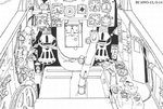
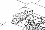
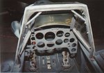
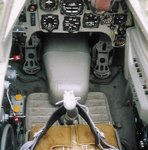
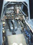
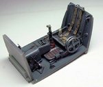
as you can see here
http://www.ww2aircraft.net/forum/start-finish-builds/1-32-hasegawa-bf-109-g-14-a-25857.html
I started building the Hasegawa BF 109 G-14.
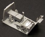
For cockpit details I'm using the MDC kit that's quite good but absolutely not clear to me on how to assembly the rudder pedals, also because instructions are very basic

PE parts no. 24 are nice but are them to be back supported by something? There are little resin parts probably to be used for this, but how?
Does anybody have a drawing or picture of these rudder pedals and how they were installed?
Many thanks in advance
Alberto
as you can see here
http://www.ww2aircraft.net/forum/start-finish-builds/1-32-hasegawa-bf-109-g-14-a-25857.html
I started building the Hasegawa BF 109 G-14.
For cockpit details I'm using the MDC kit that's quite good but absolutely not clear to me on how to assembly the rudder pedals, also because instructions are very basic
PE parts no. 24 are nice but are them to be back supported by something? There are little resin parts probably to be used for this, but how?
Does anybody have a drawing or picture of these rudder pedals and how they were installed?
Many thanks in advance
Alberto


")