Need help identifying old generators

Ad: This forum contains affiliate links to products on Amazon and eBay. More information in Terms and rules

letsurf

Recruit
1
0
May 26, 2025
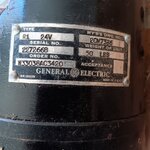
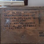
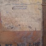
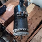
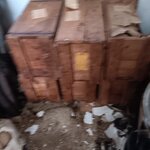
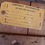
My dad purchased these many years ago at an auction. They are still in the original crates and look new. He's trying to find out what they are, what kind of aircraft they were used for, and if people still use them when restoring old planes. He would like to sell them eventually but doesn't even know where to start or what they are worth.
 

Attachments

  • 8407232071551103355.jpg
    8407232071551103355.jpg
    116.8 KB · Views: 37
  • -2968501035769322552.jpg
    -2968501035769322552.jpg
    95.7 KB · Views: 31
  • -5480895640989022195.jpg
    -5480895640989022195.jpg
    88.3 KB · Views: 31
  • 5408715005778206226.jpg
    5408715005778206226.jpg
    106.7 KB · Views: 33
  • -6561808829710878339.jpg
    -6561808829710878339.jpg
    95 KB · Views: 30
  • -1918118711102148722.jpg
    -1918118711102148722.jpg
    95.3 KB · Views: 33
I poked around on Google and learned not much except a DC self exciting 24 volt generator. I get the impression it is a multi application unit so many engines will have an accessory pad to fit it. Yours have some rust on the splines. These must be overhauled before use. My guess is your cores have some value.
 
Well, you have some clues. 1) It turns at a continuous duty 8000 RPM. 2) It's got a max rating of 300 amps. 3) It's a 24 VDC system generator. 4) The tag clearly states "Army" use. I'm thinking helicopter. The tag also states it is neither marked for use or scrap, giving us some notion that it's meant for re-utilization storage.

The question now is to ask what 24 volt system aircraft accessory drive gearbox has a geared pad designed for a continuous 8,000 RPM? That's a very high RPM. Most turn somewhere between 5 to 6,000 RPM, IIRC. Plus, it's self-excited, meaning there's no external controller. Last, it has a 24 bolt flange meaning between its weight (50 Lbs) and torsional load while delivering its full current load demand it needs a beefy accessory pad.

Edit to add: Reading further about the National Stock Number (6115-00-149-1536), it might have been used in a ground power generator set.


I'd value it at the current price of scrap copper, to be honest.
 
Last edited:
All I can add is the 8,000 RPM to me means Turbine Engine Helicopter, and on most Helicopters I worked on the Generator was usually mounted on the Transmission not the engine.
 
AirCorps Library shows the following document:
AN 03-5AD-17 Operation, Service and Overhaul Instructions with Parts Catalog for Aircraft Generators - Models 2CM73B1 and 2CM73B5
Revision Date: 1-Aug-1945

I assume that 2CM73B6 is similar to these, but I can't find a specific manual for it. However there is a Ford Motor Company 2CM73B6 generator for sale on e-bay, and it looks very similar to your pictures.
 
All I can add is the 8,000 RPM to me means Turbine Engine Helicopter, and on most Helicopters I worked on the Generator was usually mounted on the Transmission not the engine.

This is a 1945 1943 unit. There were no turbine engined helicopters in 1945 1943 and very few, if any, piston engined helicopters that required a 300amp generator.

EDIT two typos corrected.
 
Last edited:
The P-1 was a common generator on Army Air Force aircraft, came in multiple versions, and used on multiple aircraft of the period. You will need to look at parts catalogues to determine which specific aircraft types. Like most generators of the time it does require a voltage regulator and a control relay.

1748558647495.png
1748558738402.png
 
This is a 1945 unit. There were no turbine engined helicopters in 1945 and very few, if any, piston engined helicopters that required a 300amp generator.

If I may ... the 2CM73B1 and 2CM73B5 seems to be the 1944/1945 units. But the requested one is the 2CM73B6 type and not necessarily being of the same time. I would say it can be a post-war device. The date on the record card could help but it is not readable in the pic unfortunately.

date.jpg


and BTW ... not the P-1 but R-1 as it is written on the box.
 
Whoops - you are right, it is R-1. This is from the same Dec 43 manual as the above. So I am not only blind but did a typo. I will blame it on that Japanese disease Oldage, or is it Mexican Ol Dage - too old to remember.

Regarding the 12 mount points shown in the manual (and 24 on the actual units) - all engine generator pads have only six studs. The 12 or 24 holes are to allow the unit to be rotated in 12 or 24 different directions to suit the engine mounts, generator cooling tubing, engine plumbing, wiring harness, etc etc.

Later generators tended to have 12 keyhole slots as holding up a unit weighing 40+ pounds in a confined space while trying to start the top nut with the other hand is what is politely called a right proper b*****d. Being able to leave the top nut on, slide it over and rotate a small amount to "lock" from falling off makes life far more pleasant.

1748572725872.png
 
That would mean that Manual for the Jack and Heintz generator meeting the R-1 spec was introduced about that date. That TO was renumbered around 1953 to T.O. No. 8D6-5-5-1 and the manual was still being updated in late 55 so it was a common unit for many years.

It is not uncommon for the official manuals for new equipment to be produced months after the unit goes into production. In the interim the manufacturer provides a draft manual - usually with each unit produced - and the feedback from users on that document results in the official manual. Usually these manuals are labelled as Provisional manuals and sometimes the USAAF also printed those manuals as a provisional manual. Most manufacturers had staff imbedded in major customers for the introduction of new equipment and part of their job is to collect feedback on the deficiencies in the companies documentation. This still applies today.

Like with the P-1 there would have been more than one manufacturer and my post being from manual 00-25-10 Vol 3 dated Dec 43 Jack and Heintz had produced at least one by then as the unit was listed as under procurement.

The photo in 00-25-10 Vol 3 is identified as a J&H model JH2000 covered by 03-5AG-2.

The first manual for the GE version that L letsurf provided photos of was 03-5AD-14 dated 25 May 45.

1748652414062.png


There may have been a Delco Remy, Leece Neville and/or Westinghouse R-1 generator but I have no evidence to support that. All were a major suppliers in that time frame and all made versions of the P-1.
 
Last edited:

Users who are viewing this thread

Back