View attachment 901952
This diagram from Tom's post can give some help with understanding the type of pitch changing gear operation. I will add that the small planet type gears are mounted on bearings on the small axles shown so that they can turn. A main factor is that gears J, K and M are cut on the same diameter but with different numbers of teeth that are designed with profiles and clearances that allow the planet teeth to engage with both at the same time.
If we consider the action of adjusting pitch, it is achieved by turning gear C, which rotates gear G and its joined axles carrying planet gear H which in turn moves gear K by 4/86 for every full revolution of gear G. In turn, gear K turns planet gear L and so turns gear M through a total of 4/86 x 86/82 = approx 1/25 of a revolution for each revolution of gear G, regardless of direction or speed of the propshaft or the input. The gear M is linked to gear N which inputs the pitch change gear P at a ratio of around x4 and so the blade pitch is adjusted.
There are two points to note from the diagram notes. Firstly, none of the gears are "free to spin", they are all permanently engaged but the whole gear train from C to P can vary its relative position to gear J.
Secondly, I was not aware that the patent by Robert Stanley applied and I have not seen that before!
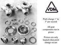
Also, the pic on the RHS is of the early type of VDM mechanism and hub, fitted to a JUMO 211 engine.
Cheers
Eng