Pusher Propellers/B-36 'PeaceMaker'....

Ad: This forum contains affiliate links to products on Amazon and eBay. More information in Terms and rules

xylstra

Airman 1st Class
197
58
Jul 9, 2014
Pusher-propeller configured aircraft designs possess many desirable attributes however, one of the few de-merits levelled against this layout is the issue of engine cooling during ground-running on the basis that tractor-mounted engines recieve a more direct blast of cooling air from the propeller slipstraem in front. 'Phooey"!! - I'm un-convinced! From what I understand the largest volume of airflow generated by a revolving propeller is produced from the outer 1/3 to ½ of the blade disc area which washes past the engine cowling leaving the 'core' in the wind-shadow, minimal at best and probably not much in excess of the induced flow through the cowling of a rear-mounted engine just in front of the propeller.
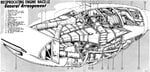
It immediately brings to mind the effectiveness of the air-cooling system for the P&W R-4360 28-cylinder aero-engines used in the B-36 bomber. I have little knowledge of the set-up. Can anyone describe whether supplementary cooling air was provided via auxilliary fans, perhaps a special P&W variant of this engine? What operational restrictions were applied to the B-36 for extended ground-running/ambient temperature limitations?
Any further comments on the topic in general are welcome......
 
Some piston engine tractor type propellers did have cuffs added to the blade roots to add in engine cooling, example some P-51 did have cuffs for the desert, while most did not.
Also some blades had increased width in the root area for increased engine cooling effect, example the blades used on the DC-4, 6507A-0, were similar to blade used on the Lancaster, 6519A-0, built in Canada, the outer 2/3 of the blade had the same width, thickness, angles and tip platform; but the Lancaster blade had a wider cord in the root area to aid in engine cooling.
 
Why would propeller cuffs make any difference to cooling on a P-51?

Most US air-cooled aircraft did without spinners or cuffs.
 
An expert description of the R-4360 and prope
handbook GRB-36D-III 10-11 l.jpg
ller installation in the B-36 can be found in Graham White's "R-4360: Pratt & Whitney's Major Miracle". The R-4360 had a cooling fan on the accessory end of the engine and airflow through the cowling system was controlled by overlapping "iris" type shutters at the end of the cowling just before the pusher propellers . Not shown in the photo, but the cooling fan was located just under that double cowling frame towards the center of the photograph. Photo from The Cold War - Ramey Air Force Base Historical Association .
B-36.jpg
 

Attachments

  • handbook GRB-36D-III 10-11 l.jpg
    handbook GRB-36D-III 10-11 l.jpg
    228 KB · Views: 1,765
True, virtually all of the viable thrust of a propeller is from beyond the outer half of the blade span, but that doesn't mean prop cuffs did nothing. The two things cuffs did were 1) provide airflow for improved ground cooling in that, while they couldn't move the aircraft, they could move air* and 2) they streamlined the root end of the blade for less drag during high speed flight.

*This was almost exclusively for aircooled engines.

A primary advantage of pusher props is the high speed prop blast isn't flowing around the airframe causing more drag (the faster the airflow around an airframe the more drag). A notable example of this effect is the Do335 which in single engine operation is 48mph faster on the rear engine than the front despite the rear prop being smaller*. The Cessna 336/337 was also faster on the rear engine.

*The rear prop blades were cut down almost 4 inches each to reduce their higher (than the front prop's) tip speed due to running in the high speed airflow from the front prop.
 
According to Myers Jacobsen, "The first Pratt & Whitney R-4360-5P Wasp Major test engine was to have been handmade and delivered to Fort Worth in May 1943. Design improvements delayed it until October, but by December, the full-scale wind tunnel tests were begun in Wright Field's 20-foot wind tunnel... As it had been delivered from Pratt and Whitney, the R-4360-5P engine was equipped with a type 11-11A cooling fan, designed to be in operation continuously while the engine was running. The engine cooling tests were run through 1944 and into 1945, during which time seven different fans were tested. The 11-11A type was replaced with a 34-blade fan, and the air diffuser tunnel was belled out to increase its cross sectional area within the nacelle. This slowed down the air and greatly improved the cooling."

Nevertheless, when flight tests began, "two of the main problems to manifest themselves were lack of proper engine cooling and propeller vibration stress, although both of these situations had been extensively investigated in the wind tunnel test programs. Engine cooling became a problem that would result in the inability of the XB-36 to maintain high altitude operations for extended periods of time above 30,000 feet. A two speed cooling fan was later developed to keep engine temperatures within safe operating limits."

Air entering the upper intake on the wing leading edge went to the intercoolers and the engine cooling fan. The lower intake supplied the oil coolers. The turbos also inhaled through this intake. Each engine had two turbos and two intercoolers. Exit shutters for the latter were on top of the wing, in appearance similar to Venetian blinds either side of each nacelle.

Instead of cowl flaps, the B-36 had "air plugs" which were adjusted fore and aft by electric motors to throttle cooling air at the exit. A pattern of four diamonds on each air plug indicated its position to the gunners in the aft compartment, who could report this to the engineers. Observation of conditions on the wing trailing edge by the two lower rear gunners was so vital, there was an emergency interphone power circuit for them, the engineers, and the pilots. It allowed those six men to communicate in the event of total AC failure.

In addition to low and high fan speeds, late B-36s had a neutral setting to disengage fan drive. The flight manual says, "In the event that CHT cannot be maintained high enough for proper engine operation and if carburetor heat, almost closed air plugs, single turbo, etc. operation does not bring CHT up sufficiently; then, as a last resort neutral fan operation may be used." In neutral fan there were more restrictive limits on CHT and rpm since the hottest cylinder could much exceed one of the four you could select on the CHT gauge.

There were limits on high fan operation too. Below 15,000 feet it was possible to overstress the fan if rpm limits were not observed. Normally high fan went with high altitude. The manual says, "The rate at which the heat is removed from the head is dependent upon the weight of the cooling air flow and the temperature difference between the head material and the cooling air... These two factors work in opposing directions as the altitude of operation is increased. The decreasing temperature is favorable as it widens the temperature difference of the heat exchange. Unfortunately the decreasing air density, which is unfavorable, reduces the rate of cooling air flow at a rate that overcomes the beneficial temperature factor. If constant power is maintained at high altitude, the cylinder cooling problem becomes increasingly difficult."

On the other hand, during ground operation the Wasp Majors could become too cool: "During idling, an attempt should be made to maintain cylinder head temperatures between 170° to 220°C by use of the air plugs. This will minimize the possibility of spark plug fouling. Normally, high idle speed will not be used to keep cylinder head temperature high. However, if these temperatures cannot be maintained with the air plugs, it may be necessary to use higher idle speeds."

Low fan was the normal setting for all ground operation, except for a quick check of high fan during run-up.

References:

Meyers K. Jacobsen, "Convair B-36," 1997.

AN 01-5EUG-1, "Flight Handbook USAF Series B-36H Aircraft," 1953.
Convair B-36 H Aircraft Flight Manual 01-5EUG-1

I have purchased manuals from that company several times. Their scans are of excellent quality and flight manuals include the performance supplement. They are in Italy, but discs reach me in California in 10 days. The one time the discs never arrived, they gave me an internet download.
 
Pushers are more efficient for the reasons suggested, but few pushers have ever been successful after, say, 1916. In terms of WW2 fighters there were all sorts of prototypes of flying wings, canards, twin-boom pushers but not one proved better in real life than a conventional layout. In fact of all the prop fighter monoplanes the only departure from convention was the P39/63 family, everything else tractor front-engine low to mid wing. Oh and working in the wing wake makes the prop fatigue faster.
 
One of the more interesting things for me about the B-36 was how to change the ram-air cooled P&W R-4360 engines into pushers. After rebuilding two R-2800s and seeing their structure, I could not see how it was easy to turn the engine around to become a pusher and maintain the ram air cooled aspect. I cannot believe a fan would be the only source of cooling.

From my inquiries and investigations it appears P&W engineers must have had some foresight to make this relatively easy. P&W radials have each cylinder bolted to the crankcase with approx. 35 nuts on studs. Each cylinder has appropriate baffles to direct cooling around the cylinder. What they did for the B-36 was to remove each cylinder and rotate them 180 degrees so the baffles faced where any ram air would be deflected. Then some re-routing of the intake and exhaust tubing for the cylinders, and last resetting the cam timing. The engine could then be mounted as a pusher.

I was told all this by a retired AF colonel and have never looked at any 4360s or images of them mounted close up to confirm. But the drawing above shows the carburetor at the forward end of the engine which is consistent and also shows the turbo forward which is also consistent with a standard 4360 mounting.

I didn't consider but assume the prop blade angles would have to be set differently since a normal right hand screw would not work.

Tony
For the propellers, most Hamilton Standard Props i.e. 23E50 as used on a C-47, the blades can be run as either a Tractor Propeller or if you move a lug on the brass blade busing, they can be set up as a Pusher Propeller by installing the gear segment on the blade butt on the other side. This propeller direction of rotation would not be correct for a standard R/H rotation engine, then you either have to change to a L/H rotation propeller, or change the engine gear box to turn the propeller shaft the other direction.
 
Hi Guys,
Have read all the exchanges with great interest - certainly been educational! Probably the (supposed!) cooling issue arising from the pusher configuration with respect to piston aero-engines is probably more related to water-cooled engines though either a supplementary fan or perhaps even an in-cowl, annular radiator (ala German WW2 installations) might do the trick but air-cooling looks perfectly fine in the rear-mounted configuration.
One poster suggested an increase in prop fatigue. I'm un-convinced! Far more likely is an increase in abrasion and edge-erosion due to grit and FO's being thrown into the blades by the undercarriage wheels from seldom sweeped tarmacs. Mind you, I've seen quite a few tractor propellers with a remarkable amount of dings, dents and abrasive scuffs - only practical experience will be the judge.
Thanks again, and keep it coming. Cheers.
 
One of the more interesting things for me about the B-36 was how to change the ram-air cooled P&W R-4360 engines into pushers. After rebuilding two R-2800s and seeing their structure, I could not see how it was easy to turn the engine around to become a pusher and maintain the ram air cooled aspect. I cannot believe a fan would be the only source of cooling.

From my inquiries and investigations it appears P&W engineers must have had some foresight to make this relatively easy. P&W radials have each cylinder bolted to the crankcase with approx. 35 nuts on studs. Each cylinder has appropriate baffles to direct cooling around the cylinder. What they did for the B-36 was to remove each cylinder and rotate them 180 degrees so the baffles faced where any ram air would be deflected. Then some re-routing of the intake and exhaust tubing for the cylinders, and last resetting the cam timing. The engine could then be mounted as a pusher.

I was told all this by a retired AF colonel and have never looked at any 4360s or images of them mounted close up to confirm. But the drawing above shows the carburetor at the forward end of the engine which is consistent and also shows the turbo forward which is also consistent with a standard 4360 mounting.

I didn't consider but assume the prop blade angles would have to be set differently since a normal right hand screw would not work.

Tony

I imagine that the supercharger, carburettor and intake piping would be an issue for reverse cooling flow.
 
Hi Guys,
Have read all the exchanges with great interest - certainly been educational! Probably the (supposed!) cooling issue arising from the pusher configuration with respect to piston aero-engines is probably more related to water-cooled engines though either a supplementary fan or perhaps even an in-cowl, annular radiator (ala German WW2 installations) might do the trick but air-cooling looks perfectly fine in the rear-mounted configuration.

I don't think air cooled engines were "perfectly fine" for pusher installations without the use of a cooling fan.

Liquid cooled engines in pusher configurations suffered from low air flow between the engine and cowl, which was usually quite tight. The cooling systems themselves, were fine.
 
One poster suggested an increase in prop fatigue. I'm un-convinced! Far more likely is an increase in abrasion and edge-erosion due to grit and FO's being thrown into the blades by the undercarriage wheels from seldom sweeped tarmacs. Mind you, I've seen quite a few tractor propellers with a remarkable amount of dings, dents and abrasive scuffs - only practical experience will be the judge.
The theory is that the prop is operating in the turbulent air of the wing and cowling, leading to more blade flexing and fatigue.
Pusher installations and swept wing installations may cause 2P, 3P, 4P, and other harmonic excitations of both major and minor axis modes due to the disturbances to the airflow into the propeller disc. These higher order excitations may become dominant if there is a critical speed in the propeller operating range.
Typical forces are the firing impulses from a reciprocating engine; aerodynamic forces from ground cross-winds; and aerodynamic forces from the wake of the airplane on pusher installations
. - FAA AC20-66
 
The pusher configuration was indeed stressful for the propellers. Jacobsen says,

"Although the Moffett Field wind tunnel tests had been passed satisfactorily, and had given some sense of the vibration stress that was to be expected, the pusher configuration and the attendant punishment imposed on the wing flap structure, engines and propellers was greater than anticipated... Under clean wing conditions, and within a fairly wide speed range, the propeller vibration stress was acceptable, but additional stress occurred with flaps down or under high power settings, such as experienced in a climb or a field go-round. No aerodynamic means of eliminating the reactions caused by passage of the propeller blade through the wing wake could be found, so the affected structures were strengthened and new rpm, speed, and altitude combinations were specified for flight operations."

To be fair, that was not unique to the B-36. The C-124 also used the Wasp Major and it too had prohibited combinations of airspeed and rpm.

With regard to the conversion from tractor to pusher, the Wasp Major had a modular design to accommodate configuration changes, According to Armbruster, "In the final designs of the R-4360, it was possible to take any power section and convert it to a tractor or pusher model by changing only the cams, reversing the cylinders and changing the intake pipes and baffles. This same basic power section was used on all the multiplicity of models designated R-4360. A similar application was made to the rear section where converting from single to auxiliary stage involves little more than the removing of a rear cover plate and substituting the additional stages... The object of this was to manufacture an engine that could be easily converted to any number of models without having to have a great number of different machine operations for each..."

In the B-36 installation there were deflectors to guide air around the carburetor, as otherwise it would obstruct airflow to the upper cylinders.

References:

Myers K. Jacobsen, "Convair B-36," 1997.

G.E. Armbruster, "History of the R-4360," http://www.enginehistory.org/Piston/P&W/R-4360/r-4360.shtml

The bit about the air deflectors I read in a USAF instruction manual which appeared to have been prepared for maintenance troops going through tech school. It was somewhere online, but for the life of me I can't find a reference.
 
Prop fatigue because each blade travels through the wing wake twice per revolution rather than working in clean air. Wish I could remember where I got that from, I seem to recall a raceplane designer.
 
Prop fatigue because each blade travels through the wing wake twice per revolution rather than working in clean air. Wish I could remember where I got that from, I seem to recall a raceplane designer.
I've read that's why the Piaggio P.180 is so loud and buzzy, to the point that some airports ban it.

As for WW2, one of my favourite pushers is the Mansyū Ki-98.
 

Users who are viewing this thread

Back