Relevance of engine-balance and timing issues affecting master-and-slave connecting rods.

70
19
Joined
Nov 26, 2025
A.H.H here.
After a brief intermission as I get myself back home from school and resituated in my life, I return with another rather complex investigation.

As someone who likes when things "just work out right", it was quite annoying for me to realize that the non-master pistons of engines using master-and-slave rods are a little "off" in almost every conceivable way. From the piston speed (and all the associated derivatives), to the phases in which it moves, to the compression ratio....

I am aware that the largest elements of these issues were at least partially addressed. For example, the lengths of the slave rods, and their position of attachment to the shared "big end", were intentionally varied. I presume this was to preserve appropriate TDC timing without quite as big a change in stroke length, as would occur if all rods were spaced equally about the crank.
Master rod and links.JPG

Visible here is the varied spacing of the rods, in this photo from cheetah3d.com. It is hard to make out the associated difference in rod length.

Was this level of micromanagement (different rods, spacings, possibly also spark timings.....) done outside the great increase in engine quality and power that was the second world war?
Was there ever any attempt made to tackle the nuisance of balancing this minor element of the typical ww2 radial? Obviously the crank counterweight is 99% of the battle, but every little bit helps!
I will provide an interesting alternative rod design below that saw great service in world war one, but I have not been able to determine if it was intended to have any benefits over the conventional system depicted above. It is very possible that any simplification of engine dynamics was just a happy accident.
imageedit_9_2061771914_0.png


The Le Rhône 9c (if not also its siblings, predecessors, and progeny, on which this sort of information is more scarce) did not use a typical shared big end, but instead used a complex system of "duck-footed" rods (think of a typical inline rod but missing the cap and associated bolts) held in place by grooves and shoulders on a dish about the size of the shared big end in the image above, which was (rigidly?) fixed to the crank.
For those not sated by the above image, (from thevintageaviator.co.nz) here is an animation of the assembly process.

View: https://www.youtube.com/watch?v=th-GuQ7OMSc
I would highly recommend giving this a watch.

In addition to doing away with the aforementioned minor timing nuisances, this method of construction also would have a reduced manufacturing complexity compared to a more modern radial, as only 3 different forms of rod are needed for a 9-cylinder compared to the 5 of the image above. Obviously there were downsides as well (or we might see a modern equivalent in the skies today), but this element of the design struck me as pretty remarkable.

However, there are other excessively complicated means of overcoming this minor issue!
Both were used by the generator (among other things) company Nordberg.

Both their spark and diesel 11-cylinder models used a system of gears (again without a master rod) to identically control the movement of the pistons. (Image from Old Machine Press)
11CylinderNordberg.PNG

Again, I have not been able to determine if this was done to rectify minor timing and balance issues or for other reasons.

The weight alone makes this unsuitable for aircraft, I imagine. On the plus side, it probably makes for a more efficient generator - whether through improving dynamic properties, maintenance, manufacture, or some combination thereof.
Not satisfied with one unorthodox means of controlling the rods of a radial, Nordberg produced an entirely different design for their 12 cylinder engines. (Image again from Old Machine Press)
12CylinderNordberg.PNG

This mechanism used "restraining cranks" on a pair of opposing cylinders. Perhaps sort of like a watts linkage? Was this possible only because of the even cylinder count?

One thing this reminds me of is the system for controlling the sleeve valves on the Rolls-Royce Crecy. (GIF from whatifmodellers.com)
proxy.gif

There may be no relation, but using an additional "piston" (of different stroke and throw) to police the movement of the primary two is interesting nonetheless.
Either system seems like it would introduce further balance issues. If anyone has an idea what incentivized not using the geared mechanism instead (or vice versa) I am all ears.

Where engine design during the war was concerned, was there every any discussion of the ways these minor issues cropped up? I would imagine that there would be either a "limiting cylinder" in terms of fuel mixture, cooling, and lifespan - or the need to individually control the feed to each cylinder (not really possible without per-cylinder injection). In the never-ending pursuit for more power, I imagine someone would have set their eyes on this at some point. Unfortunately I have found no mention of this.

Good old fork-and-blade rods never seemed so elegant. I think I will keep my design exercises to inline engines, at least for the time being!
Thanks for any insights shared.

P.S. WEBP is an evil image format and should not be permitted to exist on this fine earth. I have had to manually convert the Nordberg images to PNGs by screenshotting them and saving them myself.
P.P.S How do I post a Youtube link without the thumbnail? I have had to pass up on linking the video in the glossary lest it needlessly appear a second time.

Links in order of appearance:
Radial Engine Animation WIP (Image 1)
Le Rhône 9C Engine History | The Vintage Aviator (Image 2)
Le Rhône 9C - Assembly Movie (HD) (Video link)
Nordberg Radial Stationary Engine (Images 3 and 4)
The Crecy Engine (GIF)
 
Last edited:

Attachments

I can't add any engineering expertise to this, and the video is very interesting, but you are comparing 2 different engine types construction, a radial, and a rotary. They operate in very different ways, power levels and have very different stresses. You have to keep in mind that a rotary engines pistons do not actually reciprocate, they orbit around the crankshaft. So the stresses they have to cope with are very different compared the radial engines design.

Also consider that rotary engines basically operated at full throttle all the time, there is no throttle to speak of. So constant speed and power setting (granted it was full power all the time). A radial engine has conventional throttle so it operated at many power settings and variable speeds. Granted most of the time would be spent below the full throttle setting.

Not to mention the 30 years or so between the engines design stages, and the vast engineering advances that were made between 1905-1935.

Just a couple of more things to consider when looking at similar looking but very different designs.
 
Whilst we await someone who actually knows the answer to your questions, I will throw in some pertinent data:
1. Bristol Centaurus Master Rod drawing from the excellent Ellsworth Hovey Getchell Foundation Archives: Ellsworth Hovey Getchell Foundation Archives | Home
2. The fork and blade can also be made complicated: Why did fork-and-blade conrods disappear post-WWII?

Incidentally, In the 1970's at the RAF No1 School of Technical Training, RAF Halton, we had a magnificent cut-away Bristol Centaurus engine, as part of the Engine Workshops engine display. This fantastic engine was cut-away in masterly style, with all of the internal working parts exposed and approx 6 of the cylinders on the Port side removed to reveal all details.
A crowning glory of this display engine was that it could be cranked-over by an electric motor at about 15rpm and the complex movements of the cranks, rods, pistons gears, sleeves and pumps was fully revealed. I did spend a deal of time studying this fantastic Beast!
I would be interested where this engine lives today?

Eng
 
A.H.H here.
After a brief intermission as I get myself back home from school and resituated in my life, I return with another rather complex investigation.

As someone who likes when things "just work out right", it was quite annoying for me to realize that the non-master pistons of engines using master-and-slave rods are a little "off" in almost every conceivable way. From the piston speed (and all the associated derivatives), to the phases in which it moves, to the compression ratio....

I am aware that the largest elements of these issues were at least partially addressed. For example, the lengths of the slave rods, and their position of attachment to the shared "big end", were intentionally varied. I presume this was to preserve appropriate TDC timing without quite as big a change in stroke length, as would occur if all rods were spaced equally about the crank.
View attachment 878464
Visible here is the varied spacing of the rods, in this photo from cheetah3d.com. It is hard to make out the associated difference in rod length.

Was this level of micromanagement (different rods, spacings, possibly also spark timings.....) done outside the great increase in engine quality and power that was the second world war?
Was there ever any attempt made to tackle the nuisance of balancing this minor element of the typical ww2 radial? Obviously the crank counterweight is 99% of the battle, but every little bit helps!
I will provide an interesting alternative rod design below that saw great service in world war one, but I have not been able to determine if it was intended to have any benefits over the conventional system depicted above. It is very possible that any simplification of engine dynamics was just a happy accident.
View attachment 878465

The Le Rhône 9c (if not also its siblings, predecessors, and progeny, on which this sort of information is more scarce) did not use a typical shared big end, but instead used a complex system of "duck-footed" rods (think of a typical inline rod but missing the cap and associated bolts) held in place by grooves and shoulders on a dish about the size of the shared big end in the image above, which was (rigidly?) fixed to the crank.
For those not sated by the above image, (from thevintageaviator.co.nz) here is an animation of the assembly process.

View: https://www.youtube.com/watch?v=th-GuQ7OMSc
I would highly recommend giving this a watch.

In addition to doing away with the aforementioned minor timing nuisances, this method of construction also would have a reduced manufacturing complexity compared to a more modern radial, as only 3 different forms of rod are needed for a 9-cylinder compared to the 5 of the image above. Obviously there were downsides as well (or we might see a modern equivalent in the skies today), but this element of the design struck me as pretty remarkable.

However, there are other excessively complicated means of overcoming this minor issue!
Both were used by the generator (among other things) company Nordberg.

Both their spark and diesel 11-cylinder models used a system of gears (again without a master rod) to identically control the movement of the pistons. (Image from Old Machine Press)
View attachment 878466
Again, I have not been able to determine if this was done to rectify minor timing and balance issues or for other reasons.

The weight alone makes this unsuitable for aircraft, I imagine. On the plus side, it probably makes for a more efficient generator - whether through improving dynamic properties, maintenance, manufacture, or some combination thereof.
Not satisfied with one unorthodox means of controlling the rods of a radial, Nordberg produced an entirely different design for their 12 cylinder engines. (Image again from Old Machine Press)
View attachment 878467
This mechanism used "restraining cranks" on a pair of opposing cylinders. Perhaps sort of like a watts linkage? Was this possible only because of the even cylinder count?

One thing this reminds me of is the system for controlling the sleeve valves on the Rolls-Royce Crecy. (GIF from whatifmodellers.com)
View attachment 878470
There may be no relation, but using an additional "piston" (of different stroke and throw) to police the movement of the primary two is interesting nonetheless.
Either system seems like it would introduce further balance issues. If anyone has an idea what incentivized not using the geared mechanism instead (or vice versa) I am all ears.

Where engine design during the war was concerned, was there every any discussion of the ways these minor issues cropped up? I would imagine that there would be either a "limiting cylinder" in terms of fuel mixture, cooling, and lifespan - or the need to individually control the feed to each cylinder (not really possible without per-cylinder injection). In the never-ending pursuit for more power, I imagine someone would have set their eyes on this at some point. Unfortunately I have found no mention of this.

Good old fork-and-blade rods never seemed so elegant. I think I will keep my design exercises to inline engines, at least for the time being!
Thanks for any insights shared.

P.S. WEBP is an evil image format and should not be permitted to exist on this fine earth. I have had to manually convert the Nordberg images to PNGs by screenshotting them and saving them myself.
P.P.S How do I post a Youtube link without the thumbnail? I have had to pass up on linking the video in the glossary lest it needlessly appear a second time.

Links in order of appearance:
Radial Engine Animation WIP (Image 1)
Le Rhône 9C Engine History | The Vintage Aviator (Image 2)
Le Rhône 9C - Assembly Movie (HD) (Video link)
Nordberg Radial Stationary Engine (Images 3 and 4)
The Crecy Engine (GIF)


It is interesting to consider the complications of movement involved with linkages, conrods and cranks. The basic angularity of rod movements that link linear and rotational movement creates some strange effects, not least the assymetric movements of a piston. Designers tried to minimise the worst effects of these physical effects by adjusting the precise position and form of components. However, sometimes the mitigation could become complex, as illustrated by the apparently otherwise non-functional sliding piston in the Crecy gif.
I think that, despite the sometimes awkward looking movements of components, in most relatively simple engine constructions the satisfactory function of the unit is achieved with careful design, but minimal complexity. Sometimes the less-preferred option can be the way to go. For instance, Rolls-Royce found it better to change to a Master and articulated conrod with their development of the Rolls-Royce R engine for the 1931 Schneider Trophy. Despite the issues with different stroke and ignition timing that it produced, the Articulated conrod allowed operation at higher rpm than the previous Blade and Fork rod could accept. Later technology allowed the use of Blade and Fork rods in the Merlin and Griffon engines.
So, within limits, I do think that the more complex solutions to basic engine construction are not needed. Usually, careful design and development will produce a satisfactory function, without extreme engineering solutions that bring their own problems.

Cheers

Eng
 
Just to take the discussion off on a tangent, I always wanted to see a cutaway of the Siemens-Halske counter Rotary engine that spun so I could see how they attached the engine to the airframe when both the crankshaft and crankcase rotate, but in opposite directions. And how they got the air/fuel mixture into the cylinders.

 
A few things:

While the Le Rhône is a rotary, all that mechanically differentiates rotaries from radials is what component is taken to be the fixed frame of reference - a radial using that rod design could be constructed. Do you think the differences in stress could have been a contributing factor in this choice of rod design?

I have thought of a sort of hybrid design between unaligned cylinders and a typical blade-and-fork layout, wherein the cylinders directly oppose eachother but the big-end bearings sit side-by-side, each connecting rod riding partly on the "shoulder" of the adjacent big-end bearing.
This would:
-Allow for the design, testing, and manufacture of only one rod
-Simplify the logistics of spare parts
-Partly eliminate the inferior oscillating wear pattern typical of a "blade" rod on the inside of the "fork" rod, in favour of conventional rotational wear on the crankshaft
-Probably be quite a nuisance to properly oil
Let me know if a drawing is in order.

I did not mean to suggest that the "additional piston" of the Crecy serves as a balance mechanism. As I understand it, it is only there to control the movement of the sleeve valves lest they move of their own volition. (Like a radial without a master rod)

The counter-rotary I have heard of before.... who on earth gave this the green-light?
 
While the Le Rhône is a rotary, all that mechanically differentiates rotaries from radials is what component is taken to be the fixed frame of reference - a radial using that rod design could be constructed. Do you think the differences in stress could have been a contributing factor in this choice of rod design?
I don't understand this statement, as rotary engines do not use that type of connecting rod, the Le Rhone connecting rods are not bolted around the crank shaft, they just sort of push on the crankshaft on its lower end, and they interlock with each other on the crankshaft end. And use "slipper" bearings.
1778701777710.png

1778701942045.png
 
A few things:

While the Le Rhône is a rotary, all that mechanically differentiates rotaries from radials is what component is taken to be the fixed frame of reference - a radial using that rod design could be constructed. Do you think the differences in stress could have been a contributing factor in this choice of rod design?

I have thought of a sort of hybrid design between unaligned cylinders and a typical blade-and-fork layout, wherein the cylinders directly oppose eachother but the big-end bearings sit side-by-side, each connecting rod riding partly on the "shoulder" of the adjacent big-end bearing.
This would:
-Allow for the design, testing, and manufacture of only one rod
-Simplify the logistics of spare parts
-Partly eliminate the inferior oscillating wear pattern typical of a "blade" rod on the inside of the "fork" rod, in favour of conventional rotational wear on the crankshaft
-Probably be quite a nuisance to properly oil
Let me know if a drawing is in order.

I did not mean to suggest that the "additional piston" of the Crecy serves as a balance mechanism. As I understand it, it is only there to control the movement of the sleeve valves lest they move of their own volition. (Like a radial without a master rod)

The counter-rotary I have heard of before.... who on earth gave this the green-light?
Two minor points:

- In a rotary engine, connecting rods and pistons have a purely circular motion, and therefore the stresses on the bearings have a very strong centrifugal component, significantly different from a stationary engine. This explains why the very particular shape of the "clamshell" joint is not used in the latter ones.

- It should not be forgotten that rotary engines were ultimately doomed by their gyroscopic torque, which was very significant in the ultimate models, that were larger, heavier, and faster-rotating engines. Counter-rotary engines created two opposing gyroscopic torques that canceled each other out : that from the connecting rods/pistons, which rotated in one direction, and that of the crankcase, which rotated in the other. The idea was ultimately quite logical – it can be found in the fabulous Mawen engine just before WWII.
 
I believe something is being lost in translation here - what do you mean by "that type of connecting rod"?
I never suggested that the Le Rhône bolted the rods down, only that they are prevented from moving up or down in the bore while at rest by the grooved nature of the mounting "dish".
Think of your foot while pedaling a high-end bicycle, how it is constrained vertically by the pedal and the foot-strap yet can slide forwards and backwards with ease.
Additionally, I believe the rods did not and were never intended to contact their neighbors in each tier, instead taking and giving space as necessary. A collision between them at operating speeds would not have been pretty.

A radial (as opposed to a rotary) using this sort of connecting rod attachment scheme could be built, as radials and rotaries are mechanically identical. All I am asking here is why exactly this method was not pursued further.

That is a nice picture to present the whole apparatus, by the way.
 
Bretoal, do you have an image of this Canton-Unné system?
What little is online suggests the use of individual planetary gears, which sounds distinct from the single "rectifying pair" used by Nordberg.
Wonderful connection either way.
 
Also no one has mentioned that Rotary's are also 2 stroke engines, as opposed to 4 stroke radials, so besides the different loads, there are different sequences to deal with. Also no pressure oiling only oil premixed with the fuel. I don't know how the fixed connecting rods would work without a pressure oil system.
 
Hold on a minute - where are you getting the idea that rotaries must be 2-stroke?
The animation I linked in my initial post shows the Le Rhône cylinders firing every other revolution (4-stroke).
I believe this to be consistent with the valve-gear they had.
If rotaries were always 2-stroke, we would see rotaries with even numbers of cylinders per crank throw.
Additionally, because the volume of the crankcase does not change during the operating cycle, they would need some form of pressure assistance to scavenge the cylinder and charge it again (besides the centripetal force encouraging the mix outward along the feed channels).
 
Bretoal, do you have an image of this Canton-Unné system?
What little is online suggests the use of individual planetary gears, which sounds distinct from the single "rectifying pair" used by Nordberg.
Wonderful connection either way.

No, the Salmson/Canton-Unné system only had one planetary gear. In reality, this gear was doubled to reduce stress, but the system could very well have functioned with a single gear engaging the crankshaft and the connecting rod core—though with less reliability.

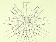
Note that this diagram shows exactly the same thing as the first photo of the Nordberg engine.
 

Attachments

  • Image1.jpg
    Image1.jpg
    130.4 KB · Views: 29
Interesting!
Do you have available any reasoning by the manufacturer for adopting that system over a "typical" arrangement?
I am curious how it was rationalized..... or if patent law was responsible.

I contest that there is any such thing as centrifugal force.
It is fictitious, as an object moving in a circle is by definition not in equilibrium and thus there is no force counteracting the centripetal component.
(Or at least that is what my rather recent physics education suggests)
I would say that centripetal force is a more reasonable term here, as it is the obstruction of the material's desire to fly off in a straight line that causes it to collect at the extremities of the rotating assembly.
 
No problem Jeff.
It is true that many rotaries share operating mechanisms with many 2-strokes, such as charging from the crankcase.
 
My bad I have an old reference book that says they are 2 strokes but apparently it is incorrect.
Many did have a strange valve system. Only one valve in the head for the exhaust. There was a valve in the top of the piston that let the mixture in from the crankcase.
These had disappeared by the end of the war. The piston located valve was weak point. warping or failing to seal properly. These engines carbon fouled very quickly and taking the cylinder off to de-carbon the pistons and heads every 20 hours (or less) was common.
The later engines used 2 (or 3?) valves in the heads.
330px-Oberursel_U.III.jpg

There was no mechanical operation of the piston valve. There was a spring and the pressure difference. On the intake stroke the low pressure in the cylinder overcame the spring and the cylinder sucked the mixture in. As long as there was positive pressure in the cylinder the piston stayed closed (in theory).

Edit. These engines did use a gas/oil mixture for lubrication. perhaps that is where the confusion comes from? The gas/oil mixture came in through the hollow fixed crankshaft and was distributed by splash/vapor to rods, pistons and cylinder walls. Oil was the famous castor oil and with the lack of any exhaust pipes to help direct the exhaust flow (only cowl sheet metal) WW I pilots had sever gastric troubles from overdosing on castor oil. These engines generally ran very rich with a high amount of castor oil in the mix.
 
Last edited:

Users who are viewing this thread

Back