AspiringHowardHughes
Airman
- 70
- Nov 26, 2025
A.H.H here.
After a brief intermission as I get myself back home from school and resituated in my life, I return with another rather complex investigation.
As someone who likes when things "just work out right", it was quite annoying for me to realize that the non-master pistons of engines using master-and-slave rods are a little "off" in almost every conceivable way. From the piston speed (and all the associated derivatives), to the phases in which it moves, to the compression ratio....
I am aware that the largest elements of these issues were at least partially addressed. For example, the lengths of the slave rods, and their position of attachment to the shared "big end", were intentionally varied. I presume this was to preserve appropriate TDC timing without quite as big a change in stroke length, as would occur if all rods were spaced equally about the crank.

Visible here is the varied spacing of the rods, in this photo from cheetah3d.com. It is hard to make out the associated difference in rod length.
Was this level of micromanagement (different rods, spacings, possibly also spark timings.....) done outside the great increase in engine quality and power that was the second world war?
Was there ever any attempt made to tackle the nuisance of balancing this minor element of the typical ww2 radial? Obviously the crank counterweight is 99% of the battle, but every little bit helps!
I will provide an interesting alternative rod design below that saw great service in world war one, but I have not been able to determine if it was intended to have any benefits over the conventional system depicted above. It is very possible that any simplification of engine dynamics was just a happy accident.

The Le Rhône 9c (if not also its siblings, predecessors, and progeny, on which this sort of information is more scarce) did not use a typical shared big end, but instead used a complex system of "duck-footed" rods (think of a typical inline rod but missing the cap and associated bolts) held in place by grooves and shoulders on a dish about the size of the shared big end in the image above, which was (rigidly?) fixed to the crank.
For those not sated by the above image, (from thevintageaviator.co.nz) here is an animation of the assembly process.
View: https://www.youtube.com/watch?v=th-GuQ7OMSc
I would highly recommend giving this a watch.
In addition to doing away with the aforementioned minor timing nuisances, this method of construction also would have a reduced manufacturing complexity compared to a more modern radial, as only 3 different forms of rod are needed for a 9-cylinder compared to the 5 of the image above. Obviously there were downsides as well (or we might see a modern equivalent in the skies today), but this element of the design struck me as pretty remarkable.
However, there are other excessively complicated means of overcoming this minor issue!
Both were used by the generator (among other things) company Nordberg.
Both their spark and diesel 11-cylinder models used a system of gears (again without a master rod) to identically control the movement of the pistons. (Image from Old Machine Press)

Again, I have not been able to determine if this was done to rectify minor timing and balance issues or for other reasons.
The weight alone makes this unsuitable for aircraft, I imagine. On the plus side, it probably makes for a more efficient generator - whether through improving dynamic properties, maintenance, manufacture, or some combination thereof.
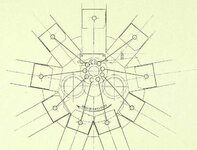
Not satisfied with one unorthodox means of controlling the rods of a radial, Nordberg produced an entirely different design for their 12 cylinder engines. (Image again from Old Machine Press)

This mechanism used "restraining cranks" on a pair of opposing cylinders. Perhaps sort of like a watts linkage? Was this possible only because of the even cylinder count?
One thing this reminds me of is the system for controlling the sleeve valves on the Rolls-Royce Crecy. (GIF from whatifmodellers.com)

There may be no relation, but using an additional "piston" (of different stroke and throw) to police the movement of the primary two is interesting nonetheless.
Either system seems like it would introduce further balance issues. If anyone has an idea what incentivized not using the geared mechanism instead (or vice versa) I am all ears.
Where engine design during the war was concerned, was there every any discussion of the ways these minor issues cropped up? I would imagine that there would be either a "limiting cylinder" in terms of fuel mixture, cooling, and lifespan - or the need to individually control the feed to each cylinder (not really possible without per-cylinder injection). In the never-ending pursuit for more power, I imagine someone would have set their eyes on this at some point. Unfortunately I have found no mention of this.
Good old fork-and-blade rods never seemed so elegant. I think I will keep my design exercises to inline engines, at least for the time being!
Thanks for any insights shared.
P.S. WEBP is an evil image format and should not be permitted to exist on this fine earth. I have had to manually convert the Nordberg images to PNGs by screenshotting them and saving them myself.
P.P.S How do I post a Youtube link without the thumbnail? I have had to pass up on linking the video in the glossary lest it needlessly appear a second time.
Links in order of appearance:
Radial Engine Animation WIP (Image 1)
Le Rhône 9C Engine History | The Vintage Aviator (Image 2)
Le Rhône 9C - Assembly Movie (HD) (Video link)
Nordberg Radial Stationary Engine (Images 3 and 4)
The Crecy Engine (GIF)
After a brief intermission as I get myself back home from school and resituated in my life, I return with another rather complex investigation.
As someone who likes when things "just work out right", it was quite annoying for me to realize that the non-master pistons of engines using master-and-slave rods are a little "off" in almost every conceivable way. From the piston speed (and all the associated derivatives), to the phases in which it moves, to the compression ratio....
I am aware that the largest elements of these issues were at least partially addressed. For example, the lengths of the slave rods, and their position of attachment to the shared "big end", were intentionally varied. I presume this was to preserve appropriate TDC timing without quite as big a change in stroke length, as would occur if all rods were spaced equally about the crank.
Visible here is the varied spacing of the rods, in this photo from cheetah3d.com. It is hard to make out the associated difference in rod length.
Was this level of micromanagement (different rods, spacings, possibly also spark timings.....) done outside the great increase in engine quality and power that was the second world war?
Was there ever any attempt made to tackle the nuisance of balancing this minor element of the typical ww2 radial? Obviously the crank counterweight is 99% of the battle, but every little bit helps!
I will provide an interesting alternative rod design below that saw great service in world war one, but I have not been able to determine if it was intended to have any benefits over the conventional system depicted above. It is very possible that any simplification of engine dynamics was just a happy accident.
The Le Rhône 9c (if not also its siblings, predecessors, and progeny, on which this sort of information is more scarce) did not use a typical shared big end, but instead used a complex system of "duck-footed" rods (think of a typical inline rod but missing the cap and associated bolts) held in place by grooves and shoulders on a dish about the size of the shared big end in the image above, which was (rigidly?) fixed to the crank.
For those not sated by the above image, (from thevintageaviator.co.nz) here is an animation of the assembly process.
View: https://www.youtube.com/watch?v=th-GuQ7OMSc
I would highly recommend giving this a watch.
In addition to doing away with the aforementioned minor timing nuisances, this method of construction also would have a reduced manufacturing complexity compared to a more modern radial, as only 3 different forms of rod are needed for a 9-cylinder compared to the 5 of the image above. Obviously there were downsides as well (or we might see a modern equivalent in the skies today), but this element of the design struck me as pretty remarkable.
However, there are other excessively complicated means of overcoming this minor issue!
Both were used by the generator (among other things) company Nordberg.
Both their spark and diesel 11-cylinder models used a system of gears (again without a master rod) to identically control the movement of the pistons. (Image from Old Machine Press)
Again, I have not been able to determine if this was done to rectify minor timing and balance issues or for other reasons.
The weight alone makes this unsuitable for aircraft, I imagine. On the plus side, it probably makes for a more efficient generator - whether through improving dynamic properties, maintenance, manufacture, or some combination thereof.
Not satisfied with one unorthodox means of controlling the rods of a radial, Nordberg produced an entirely different design for their 12 cylinder engines. (Image again from Old Machine Press)
This mechanism used "restraining cranks" on a pair of opposing cylinders. Perhaps sort of like a watts linkage? Was this possible only because of the even cylinder count?
One thing this reminds me of is the system for controlling the sleeve valves on the Rolls-Royce Crecy. (GIF from whatifmodellers.com)
There may be no relation, but using an additional "piston" (of different stroke and throw) to police the movement of the primary two is interesting nonetheless.
Either system seems like it would introduce further balance issues. If anyone has an idea what incentivized not using the geared mechanism instead (or vice versa) I am all ears.
Where engine design during the war was concerned, was there every any discussion of the ways these minor issues cropped up? I would imagine that there would be either a "limiting cylinder" in terms of fuel mixture, cooling, and lifespan - or the need to individually control the feed to each cylinder (not really possible without per-cylinder injection). In the never-ending pursuit for more power, I imagine someone would have set their eyes on this at some point. Unfortunately I have found no mention of this.
Good old fork-and-blade rods never seemed so elegant. I think I will keep my design exercises to inline engines, at least for the time being!
Thanks for any insights shared.
P.S. WEBP is an evil image format and should not be permitted to exist on this fine earth. I have had to manually convert the Nordberg images to PNGs by screenshotting them and saving them myself.
P.P.S How do I post a Youtube link without the thumbnail? I have had to pass up on linking the video in the glossary lest it needlessly appear a second time.
Links in order of appearance:
Radial Engine Animation WIP (Image 1)
Le Rhône 9C Engine History | The Vintage Aviator (Image 2)
Le Rhône 9C - Assembly Movie (HD) (Video link)
Nordberg Radial Stationary Engine (Images 3 and 4)
The Crecy Engine (GIF)
Last edited: