Bozothenutter
Airman
- 56
- Feb 10, 2021
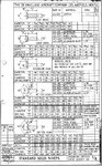
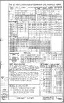
What would be the size range of rivets used in WW2?
Guessing 5 - 15 mm range?
Modelers question, just got a set if injection needles, smallest size is 0.15 mm.
So I'm guessing they can only be used for the larger sizes.
Guessing 5 - 15 mm range?
Modelers question, just got a set if injection needles, smallest size is 0.15 mm.
So I'm guessing they can only be used for the larger sizes.
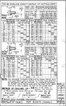
 .125 comes out at 0.066 mm in 1/48....smallest needle is 0.15...