Shorts Stirling production

Ad: This forum contains affiliate links to products on Amazon and eBay. More information in Terms and rules

Bomber Command did not send Stirlings on operations to Poland, only Lancasters went as far east as Gdynia. Danzig was to the east of Pomerania. There were two obvious targets in Pomerania, Swinemunde and Stettin but Stettin was close enough to Berlin that aircraft sent to Berlin reported attacking Stettin and plenty of Stirlings were sent to Berlin, with 64 reported losses.

When the target was actually Stettin, 29 September 1941, W7433 lost over the North Sea, W7441 shot down over the Little belt in Denmark, 20 April 1943, R9621 and BF506 reported missing, R9621 coming down at Kongsmark Denmark and BF506 SW Horsens Denmark.

On 11 October 1942 R9190 sent to lay mines off Swinemunde, shot down off Denmark.

At this point in time if the parts were definitely only fitted to a Stirling the aircraft was probably well off course when it came down, which means there are plenty of possibilities to check.
Thank you for this information, I have been checking this track and the raids on Sttetin: 29/30 09.1941 participation of 10 Stirling's from 7 Squ. 2 missing, one crashed in Jutland, the other missing.
20/21.04.1943 11 Stirlings, 1 lost over Denmark.
29/30 04.1943 ?
18/19 07.1943 ?
5/6 01. 1944 ?
I don't think any were lost over Kashubia, as that is the name of the region where this element was obtained. My question is did the Stirlings have autopilot ? Is there a possibility that they flew that long without a crew.
 
I am also inclined to this version. The first mission to Poland to drop the so-called 'Cichociemni' jumpers was carried out on the night of 15-16 February 1943. 'Cichociemni' was carried out on the night of 15-16 February 1943 in the air operation "Adolphus".
The RAF Armstrong Whitworth Whitley aircraft took off at 6.20pm from Stradishall airfield in eastern England. The six crew from Britain's 1419 Special Tasks Squadron were commanded by Capt Francis Keast. The route passed over the LaManche Canal, then over the Benelux countries, then Germany and ended in Cieszyn Silesia. Due to the length of the route, the aircraft returned to base on leftover fuel.
For my Stirling, Route 1 fit the bill.
The aircraft took off from RAF airfield, Tempsford.
Used from 1941, departing from RAF Newport, from 14 March 1942 from the secret RAF Tempsford airfield. Led north from the island of Sylt, over Denmark, at Bornholm turning south and leaving the Baltic. Over Poland, the flight headed south, over lakes Bukowo, Jamno and the distinctive Charzykowskie Lake, over Thorn to the Plock area. From there, the planes headed for the receiving posts.
So, theoretically, he was flying over Kashubia where he must have crashed.
 
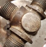
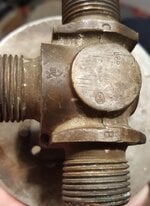
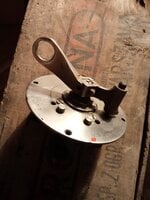
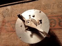
What do you think of this part, something from the fuel system of a British bomber. Which bombers had such sleekers fitted?
 

Attachments

  • nKodlLdK.jpg
    nKodlLdK.jpg
    214.1 KB · Views: 6
  • gN8NfJcZ.jpg
    gN8NfJcZ.jpg
    135.3 KB · Views: 6
  • SMr3JpSn.jpg
    SMr3JpSn.jpg
    137.7 KB · Views: 6
  • o0JHNZax.jpg
    o0JHNZax.jpg
    155 KB · Views: 5
Apart from this part, on which the number R2371 is clearly stamped, nothing else is known about this Stirling. It is a mystery I am trying to unravel.

The RAF serial number was NEVER stamped on components. On some aircraft the RAF serial of the major part was painted on by maintenance units so that they knew what aircraft a particular cowl or fairing came off as those parts did not have a serial plate on them.

To identify the aircraft type, given it is currently in dispute, you need to find a sheet metal or cast structural part from the aircraft that has a part number and an inspection stamp. Some stamps are process stamps and have no number associated with them but inspection stamps always have an inspectors number - as on these three Vickers Aircraft Castle Bromich stamps. The 3 beside the third one is the beginning of the component part number. Inspection stamps always have a border. Process stamps sometimes have a border.
1734247011407.png


The aircraft factory serial was stamped on a two small plates on every major part and again that was seldom the RAF serial. The numbers of any modifications carried out to the major component it is fitted to is stamped into the larger (modification) plate. The smaller plate is the serial plate and there were a small number of variations to the plate. These are the standard RAF/SBAC plates. On many types there is a known cross reference between the production serial number and the RAF serial number. The sample is a typical Spitfire Mod plate. the OALGS prefix to the serial is a code indicating the subcontractor who produced the assembly - in this case the optional built in signal discharger mounting kit. Note that Vickers Supermarine put the serial below the type and used the type name instead of type no.
1734245609218.png
1734246072990.png


The number R2371 on your part is therefore probably the major component part number and is the same on exactly every aircraft type that part was used on. The part number has absolutely no relationship to the aircraft serial number. You will also notice a manufacturers inspection stamp in the lower right corner partially over another number and two other longer numbers below R2371. These are probably component serial number (AGAIN never the aircraft number) and subcomponent part number. It is also possible the number R2371 is the component serial number - different manufacturers had different standards for numbering so any combination is possible and cannot be positively deciphered without knowing exactly who made the part.

Unfortunately I do not know who the HCM inspection stamp belongs to

1734240589900.png
 
Last edited:
What do you think of this part, something from the fuel system of a British bomber. Which bombers had such sleekers fitted?

Both the valve and control are standard parts used on many aircraft. The label would suggest a transfer valve.

The valve has two "inspection" stamps - one is a V and the other, next to port A, unreadable. The V is probably a process stamp but not one of the common ones. Look for other numbers cast or stamped into the valve as that can help as would a clear photo of the port A inspection stamp if it is a known one,

The valve control plate appears to have positions A to B, A to C and All off. It is a common valve used on many aircraft but the label may be specific to the aircraft type so if you can find a part number and/or inspectors stamps on that back of that this would probably reduce the field of suspects. I say may be specific to a type as most manufacturers were more specific than A to B and used a more descriptive label so the crew did not have to remember what A, B and C actually stood for.
 
Last edited:
Hey Blitz45,

Everything MiTasol said :), plus:

The first part you posted (the one that looks sort of like a crab's claw) is part of a bomb beam as used in the wing bomb cells on the Stirling. It has been torn off of the bomb beam box structure.

Stirling wing bomb cell bomb beam.jpg


On the Stirling, there were 3 wing bomb cells in each wing - between the inner engine and the fuselage - listed as inner, center, and outer. So there could be upto 6 of these bomb beams installed on a Stirling at the same time.

The Stirling could carry long range fuel tanks - 1 in each of the wing bomb cells. The 3-position switch looks like the switch for the tank cocks for these long range fuel tanks. There would be one switch per side.

The long range tanks could be installed in sets of 1, 2, or 3 per side - and could be installed asymmetrically if desired. If only 2 tanks on a side were installed they would be in the inboard and center wing bomb cell positions, while if only 1 long range tank was installed it would be in the outer wing bomb cell.

The wing bomb cell bomb beam was not used with the long range fuel tanks - there was a different set of bits and pieces used to hold the tanks in place and were not droppable - so in theory if this Stirling was carrying long range tanks there were only 5 at most.

If there were long range tanks installed then the switch wold need to be set to different positions in order to allow the fuel to be used/transferred from the various long range tanks. The switch was installed inside the fuselage near to the aft end of the tanks, and used Bowden cables to turn the actual valve in the wing near the tanks.

The 3-way pipe junction looks like it is associated with the fuel pipes for the long range fuel tanks, but I do not have any images showing this part.

re the markings on some of the parts

The number '29' was used as the prefix on Stirling specific parts and the numbers were also used in Stirling specific assembly numbers. So if a part is from a Stirling - and it is not a part or piece of equipment in general use on multiple aircraft - it should have the numbers 29 at the start of the part number or or near the start of the assembly number.

The stamp - R over 295 in a circle - is a known form of Vickers inspection stamp. The numbers 295 in the Vickers inspection stamp may be just a coincidence? I do not know if Vickers would have used dedicated inspectors for a different company's aircraft parts.
 
Last edited:

Users who are viewing this thread

Back