Hello,
Hope everything OK for each of you and thank you for the tremendous amount of information shared in this forum.
I'd like to request support from forum members about Spitfire Mk VI canopy locking mechanism please.
Spitfire boy, I'd like to get my collection updated with a Mk VI. Sounds fun to do even if Mk VI models are few and hard to get (1/72 italeri and 1/32 Hasegawa).
For modelling a Mk VI, one can do as real one was built:
As you know, Mark VI was a first attempt for a "high altitude" Spitifre to deal with Luftwaffe high altitude bombers.
Take a Mk V airframe/wings, install a Merlin 47 with 4-bladed prop, install fore and aft pressure bulkheads in cockpit, remove access door, replace sliding hood with a clamped hood, pipe engine's exhaust and underwing coolers exhaust for weapons de-icing, don't forget to add Marshall compressor inlet on R/H engine cowl for cockpit pressurization system and extend wings… putty-sand-repeat...
Tadaaaa ! You get a very strange looking but cute little known Spit (100 built airframe in total) in your collection.
That's the plan but while collecting documentation, I failed to get any details about Spitfire Mk VI canopy locking mechanism.
On 1/72, I can live without detailing this far as the cockpit is small. But On 1/48, lack of this detail may be visible… and (should be said that is the true reason), as a mechanic I like to know how thing works.
From what I could get:
Read Mark VI was fitted with a "bolted-in" (?) canopy to secure cockpit pressurization system.
A not well liked feature by the pilots as read but workable means to achieve cockpit sealing from engineer's standpoint.
Early Mark VII were equipped with such called "bolted" canopy until Lobelle system was embodied (Spitifire web site provides a splendid detailed walkaround on a swedish PR XIX where Lobelle sytem installed).
On NASM website, I could find pictures of EN 474 so equipped, and exposed in NASM (EN 474 was sent to US for tests/evaluations and preserved).
But unfortunately, there's no drawing/picture that may explain how canopy was working.
I could not imagine that pilot could be left without mean to at least open hood from the inside (especially when things need you to quickly get out the plane whatever the reason is)
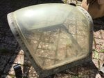
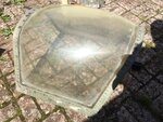
From NASM EN 474 pictures, 4 spigots are visible on hood lower rails.
I assume that once pilot was strapped in and ready to go, mechanics lifted and "clamped" hood to close the cockpit.
Then pilot would secure hood closed by moving (one? two?) handle which thru levers/rods engaged and latched spigots when canopy is installed.
This will make cockpit airtight and provide pilot with a reasonable mean to release hood whenever needed.
May be this was already discussion in this forum but I failed to found an relevant post...
Take Care
Jay-Jay
Hope everything OK for each of you and thank you for the tremendous amount of information shared in this forum.
I'd like to request support from forum members about Spitfire Mk VI canopy locking mechanism please.
Spitfire boy, I'd like to get my collection updated with a Mk VI. Sounds fun to do even if Mk VI models are few and hard to get (1/72 italeri and 1/32 Hasegawa).
For modelling a Mk VI, one can do as real one was built:
As you know, Mark VI was a first attempt for a "high altitude" Spitifre to deal with Luftwaffe high altitude bombers.
Take a Mk V airframe/wings, install a Merlin 47 with 4-bladed prop, install fore and aft pressure bulkheads in cockpit, remove access door, replace sliding hood with a clamped hood, pipe engine's exhaust and underwing coolers exhaust for weapons de-icing, don't forget to add Marshall compressor inlet on R/H engine cowl for cockpit pressurization system and extend wings… putty-sand-repeat...
Tadaaaa ! You get a very strange looking but cute little known Spit (100 built airframe in total) in your collection.
That's the plan but while collecting documentation, I failed to get any details about Spitfire Mk VI canopy locking mechanism.
On 1/72, I can live without detailing this far as the cockpit is small. But On 1/48, lack of this detail may be visible… and (should be said that is the true reason), as a mechanic I like to know how thing works.
From what I could get:
Read Mark VI was fitted with a "bolted-in" (?) canopy to secure cockpit pressurization system.
A not well liked feature by the pilots as read but workable means to achieve cockpit sealing from engineer's standpoint.
Early Mark VII were equipped with such called "bolted" canopy until Lobelle system was embodied (Spitifire web site provides a splendid detailed walkaround on a swedish PR XIX where Lobelle sytem installed).
On NASM website, I could find pictures of EN 474 so equipped, and exposed in NASM (EN 474 was sent to US for tests/evaluations and preserved).
But unfortunately, there's no drawing/picture that may explain how canopy was working.
I could not imagine that pilot could be left without mean to at least open hood from the inside (especially when things need you to quickly get out the plane whatever the reason is)
From NASM EN 474 pictures, 4 spigots are visible on hood lower rails.
I assume that once pilot was strapped in and ready to go, mechanics lifted and "clamped" hood to close the cockpit.
Then pilot would secure hood closed by moving (one? two?) handle which thru levers/rods engaged and latched spigots when canopy is installed.
This will make cockpit airtight and provide pilot with a reasonable mean to release hood whenever needed.
May be this was already discussion in this forum but I failed to found an relevant post...
Take Care
Jay-Jay
")