Superchargers?

Ad: This forum contains affiliate links to products on Amazon and eBay. More information in Terms and rules

The improvement for "Hookerizing" a DB engine might be very slight.

26.jpg

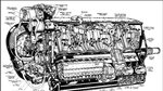
the opening to the supercharger is pretty well unobstructed. there is going to be some piping with a 90 degree bend (or close) and that is it.

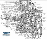
On a Merlin X engine.
Im19391207FL-RollsRoyceMerlin.jpg

the carb mount is made in one piece with the supercharger front cover and inlet. One can see the abrupt change in direction the airflow has to make and indeed one can imagine that not areas of the inlet to the supercharger (or the impeller) were handling the same airflow. In fact it is worse that this photo shows

127-5.jpg

Air from the carb has to flow up around the depression in the center of the housing to reach the upper area of the intake to the supercharger.

Back to the 109
ma_109f_2.jpg

Air intake to supercharger is well centered with little obstruction. Note mating hole in the cowl panel at the top of the picture.

There may have been a number of other differences between the DB superchargers and RR superchargers but the inlets of the DB superchargers don't appear to have the problems the early RR superchargers had.
 
Looks that there is a possibility for the air in the plenum prior to the actual impeller inlet beginning a swirl of the air and an acceleration through the wasp waisted impeller inlet housing. The larger the difference between the inlet and the circumference of the impeller, the more compression possible. Hard to tell mach about the DB setup due to the engine mount.
 
DB 601, looks to be a sidewinder type setup.
 

Attachments

  • DB 601.jpg
    DB 601.jpg
    513.5 KB · Views: 182
Hey tomo pauk,

re: "Depends who you're asking. On 2-stage V-1710s, relocating the carb from the entry of 1st stage to the entry of 2nd stage earned ~2500 ft worth of rated altitude for military power (1125 HP)."

I may be wrong but I think we are saying the same thing here, just using the carburetor in front of 2nd stage instead in front of the 1st stage on the Merlin 60 series or the only stage (on the Merlin XX anyway). The 2-stage Merlin cut-away that fliger747 linked above shows the carburetor position relative to the compressor stages. I do not know exactly how the 2-stage V-1710 is layer out, but I think the 1st and 2nd stage were separate assemblies? They may not have had a practical choice of where to put the carburetor if they wanted to get the same cooling effect from the fuel.

re: "Goes without saying that I'd love to see the tests or math predictions for S/C efficiency."

I did not download it when I ran across it back in the early 2000s, but there is a UK memorandum/wartime report/(or some other name thing) with Hooker's findings, including the mathematical descriptions o_O. I am not a theoretical mathematician (I am a semi-retired mechanical/automotive/systems/manufacturing engineer & machinist/fabricator) but I got the general idea of it. If you are up for the math it is quite interesting. Otherwise, the Rolls Royce Heritage Trust published a small booklet on Hooker's work on the supercharger in combination with the Merlin XX which gives a good explanation of what was done and why, but without the more complicated mathematical descriptions of the problem. I am sorry but I do not remember the title.

re: "Have you calculated in the losses due the carb being present?"

No. But, assuming the carburetor design had the airflow volume capability necessary, there should not be a significant impact on efficiency except when transitioning through power settings (I think?). The rammed air 'column' (my name for it) should already have been constricted to the area of the throat of the carburetor or less, and the area of the throat would be enough that only the airflow control valve should cause any increased back pressure. Pretty much the same as for a throttle body on a car but modified for higher velocity/pressure air at the entry orifice. Makes sense?Maybe?
 
Last edited:
Hey tomo pauk,

re: "Depends who you're asking. On 2-stage V-1710s, relocating the carb from the entry of 1st stage to the entry of 2nd stage earned ~2500 ft worth of rated altitude for military power (1125 HP)."

I may be wrong but I think we are saying the same thing here, just using the carburetor in front of 2nd stage instead in front of the 1st stage on the Merlin 60 series or the only stage (on the Merlin XX anyway). The 2-stage Merlin cut-away that fliger747 linked above shows the carburetor position relative to the compressor stages. I do not know exactly how the 2-stage V-1710 is layer out, but I think the 1st and 2nd stage were separate assemblies? They may not have had a practical choice of where to put the carburetor if they wanted to get the same cooling effect from the fuel.

What the Allison accomplished with carb relocated, IMO, was that it removed a source of turbulent air before a supercharger stage. That being a practical choice - fuel injected into carb cools down the compressed air after the 1st stage of compression.
Pictures of 2-stage supercharged V-1710 are easily available on the 'net, so are manuals. One picture (here) unfortunately refers the auxiliary S/C as 2-nd stage, but never the less it shows the carb attached to the inlet of auxiliary stage. Short, horizontal pipe that is used to transfer the compressed air between the stages can be also seen.

re: "Goes without saying that I'd love to see the tests or math predictions for S/C efficiency."

I did not download it when I ran across it back in the early 2000s, but there is a UK memorandum/wartime report/(or some other name thing) with Hooker's findings, including the mathematical descriptions o_O. I am not a theoretical mathematician (I am a semi-retired mechanical/automotive/systems/manufacturing engineer & machinist/fabricator) but I got the general idea of it. If you are up for the math it is quite interesting. Otherwise, the Rolls Royce Heritage Trust published a small booklet on Hooker's work on the supercharger in combination with the Merlin XX which gives a good explanation of what was done and why, but without the more complicated mathematical descriptions of the problem. I am sorry but I do not remember the title.

Thank you, I've skimmed through the paper years ago, though I don't have a book.

re: "Have you calculated in the losses due the carb being present?"

No. But, assuming the carburetor design had the airflow volume capability necessary, there should not be a significant impact on efficiency except when transitioning through power settings (I think?). The rammed air 'column' (my name for it) should already have been constricted to the area of the throat of the carburetor or less, and the area of the throat would be enough that only the airflow control valve should cause any increased back pressure. Pretty much the same as for a throttle body on a car but modified for higher velocity/pressure air at the entry orifice. Makes sense?Maybe?

It does make sense.
On the other hand, carb was not a 'no loss, just gains' mechanism. Especially the float-type carb, used also on UK-made Merlin XX (and a host of other engines), so we have a situation where replacing that type with pressure-type carb ('fuel pump' device in UK parlance) gains 8-10 mph and 1500 ft to ceiling to a Spitfire V. Test report, especially this (my bold):
The normal float type carburettor has certain inherent weaknesses, such as insufficiently precise fuel metering and distribution coupled with inability to withstand negative "g" without cutting. A fundamentally better system is to use a mechanically driven pump as the metering device with suitable compensation for altitude and boost, etc.; the metered fuel under pressure may then be injected into the supercharger intake, or direct into each cylinder.
and:
Table III shows that the aircraft is appreciably better than most other Spitfires, after allowing for differences in weight and wing span, the gain being about 1,500 ft. in ceiling and 8-10 m.p.h. in top speed. Both of these improvments may be attributed to the removal of the carburettor, causing a lower pressure drop of the engine air before entering the supercharger, and thus giving an appreciable rise in boost pressure.

Also this report by NACA, where the removal of carburetor from the 2-stage V-1710 gained between 9.5 and 25% of airflow. Carb being of pressure-injection type, so we can wonder how much of airflow would've been lost if a float-type carb was installed instead.
 
Any fuel injection system, even direct injection, needs a metering section for measuring the mass flow and adjusting such flow to effect throttling. Indeed the metering functions would perhaps have somewhat less "drag" than the restriction required to create low enough pressure in the venturi to such the fuel out in sufficient quantity for a big engine.

However the limiting factors for the engine are the ability to pack the engine with enough of a dense enough mixture to meet it's mechanical limits. Superchargers take significant engine power and the more efficient they are flow wise the less the power loss for a giver effect. The Navy was happy with their injection carburetors given the tactical environment and more moderate altitudes for Pacific combat.

Everything is a compromise and some optimal solution is chosen for some particular environment. Weight, complexity, may provide advantages in some situations and be adverse in others. Good engineering of a "simple" system is often the best.
 
This youtube video might be of interest. You can see tests, papers and such that you could look up on the net from it.

Turbo vs Supercharging in WW2 Airplanes

 
Any fuel injection system, even direct injection, needs a metering section for measuring the mass flow and adjusting such flow to effect throttling. Indeed the metering functions would perhaps have somewhat less "drag" than the restriction required to create low enough pressure in the venturi to such the fuel out in sufficient quantity for a big engine.

WW2 fuel injection systems did not use what we would call "mass flow" meters now, which were in primative form basically "Moving Vane" later refined to "Hot-wire" systems where a heated platinum wire has its resistance measured. The Moving Vane meter incites a significant pressure drop as it restricts the flow as the air is required to basically "move" a hinge. The modern hot-wire system basically has zero resistance.

In WW2 the determination of the required fuel flow was determined by virtue of a temperature sensor in the inlet tract, and a pressure sensors giving signals of external atmospheric pressure (to determine correction for exhaust backpressure) and also providing boost pressure correction relative to external pressure, which also provides correction for ram (i.e forward speed of the aircraft, in addition to normal supercharger boost). With pressure and temperature known, the mass flow can be calculated. Thus the WW2 system (although not that accurate in modern terms) does not induce ANY significant pressure drop to the inlet charge. A carburettor (except a pressure carburettor, which is basically just a primative single point fuel injector) induces a VERY significant power loss on the engine as the venturi`s needed to restrict the flow to induce the required pressure differential to suck fuel out of the float-bowl increase the pressure drop at the supercharger inlet, thereby requiring a higher supercharger pressure ratio than that requried by a fuel injected engine to achieve the same boost pressure.

Hence the direct injection metering systems provide a great deal more than just "somewhat less drag", it results in an engine power increase of about 50bhp at rated height in the case of the Merlin 46 looking at the power increase purely as a result of removing the carburettor chokes (so basically +3.5% engine power- this figure is from actual WW2 dynamometer testing, not guesswork).
 
Last edited:
Since it's a British engine some understatement is permissible. 3.5% isn't a whole bunch in the scheme of things. I am aware that WWII technology didn't include the sophistication of modern accessories, but in effect determining mass flow was what they were trying to do, match a mass of airflow to a quantity of fuel to obtain a desired mixture ratio. The DHC2 Beaver R985 which I have a lot of experience driving had fairly low volumetric power available compared to larger radials. Some of that is due to the float carb, much due to the low RPM at which it runs.

Small increments in many areas do provide meaningful engine improvement. The C series R2800 revised the oil scavenging system and in effect gained significant HP by reducing the amount of oil being slung around in the case.
 
Perhaps a bit more informative illustration?
DB 601, looks to be a sidewinder type setup.

The illustration is for a a two stage Merlin.

I was trying to show that Hooker had improved the basic RR single stage supercharger. Which , BTW, was the best supercharger in production in 1939 before Hooker modified it. And the first modification/s that he did were to the inlet cover/elbow. He continued on to do a lot more with the two stage supercharger.

DB superchargers went through a lot of changes over the years, however "Hookerizing" (modifying the inlet) wasn't going to get then much because they already had a pretty good inlet.
there may have been a few other problems with the DB supercharger though.

https://www.flightglobal.com/FlightPDFArchive/1942/1942 - 0144.PDF

Not all superchargers used the same style/type of impeller. Or housing/diffuser.

Just about all DB engines used a sidewinder supercharger (it left room for the through the prop hub gun) but since the supercharger faced the left a view from the right side obscures the inlet. Jumo engines put the supercharger (still a sidewinder) on the right side of the engine.
 
Hey Elvis,

LOL! and thanks for the laugh.

Hey tomo pauk,

I may be wrong, but:

When I look at the Merlin 2-stage cut-away I see the carburetor introducing the fuel into the eye of the rightmost, i.e. 1st supercharger stage.

For the V-1710-E11(-93) picture, what I see is the injection carburetor, which sits on top of the auxiliary stage (Allison's terminology) supercharger, metering the incoming air, and then injecting the fuel just in front of the engine stage (Allison's terminology) supercharger via the thick flexible fuel hose above the air passage tube.

In either case the fuel will absorb heat (presumably about 25ºC worth ) from the compression of air.

In the Merlin the fuel is injected and absorbs heat during the 1st stage compression, the cooled air then goes to the 2nd stage where it is heated up again, the heated air is then sent through the after cooler, then to the intake manifold.

In the V-1710-93 the air is heated by compression through the auxiliary stage supercharger, the air is then passed via the tube to the engine stage supercharger, the fuel is injected into the compression heated air at the entry to the engine stage supercharger, the injected fuel then absorbs some of the heat in the already compressed air and heat due to compression in the engine stage supercharger, the air is then sent to the intake manifold.

If both superchargers have similar mechanical efficiencies, then the following will apply:

Merlin 2-stage
Ta + T1 - 25 + T2 - TAC = MT

V-1710-93
Ta + Taux + Teng - 25 = Tm

where

Ta = Temperature of the ambient air the altitude
T1 = Temperature increase due to compression in the 1st stage
T2 = Temperature increase due to compression in the 2nd stage
TAC = Temperature decrease due to aftercooling
Taux = Temperature increase due to compression in the auxiliary stage
Teng = Temperature increase due to compression in the engine stage
Tman = Temperature in the intake manifold

If we assume that each stage is going to absorb the same amount of HP then both stages (before use of fuel for cooling) will generate the same amount of heat. If we assume the altitude is 20k ft for an ambient temperature of -25ºC, and assume the heat due to compression generated by each stage is 50ºC, then we get:

Merlin 2-stage
-25 + 50 - 25 + 50 = +50ºC - TAC

V-1710-93
-25 + 50 + 50 - 25 = +50ºC

Since the TAC will always be greater than 0, again assuming similar supercharger mechanical efficiencies, the Merlin 2-stage will be more efficient and either allow more boost at a given altitude or absorb less HP for a given amount of boost.


re: power loss due to carburetor

Sorry, I thought you meant relative to the constriction of the air flow due to the throttle valve and any other projections into the sir stream. You are of course right that the float type carburetor "draws vacuum" at the point where it sucks the fuel into the airstream. And yes the injection type carburetors are more efficient relative to this problem.
 
Depends who you're asking. On 2-stage V-1710s, relocating the carb from the entry of 1st stage to the entry of 2nd stage earned ~2500 ft worth of rated altitude for military power (1125 HP).

Something that Hookers equivalent at DB wrote in his memoirs is that in the case of a mult-stage compressor system, the priority must be given to the efficiency of the 1st stage, as detrimental inflow characteristics into the 1st stage have a far worse impact on overall compressor performance than the same restriction being applied to the 2nd or 3rd stage of a compressor. Hence if the 1710 carburettor was in any way restrictive or produced an unpleasant flow into the 1st stage compressor, it is not at all unreasonable to imagine that relocating this restriction to the 2nd stage inlet could in theory produce a gain in power. This would not be suggesting its the thermodynamic best place to put the fuel in, but reflective of the extreme importance of the 1st stage of any multi-stage compressor being optimised.

The 1710 setup with the 1st stage driven by the hydraulic coupling looks very restrictive for packaging as it sticks out the back so much , and it may well be it was impossible length wise to put the carb on the 1st stage inlet in a way that the air-path was in any way decent. However thats my opinion from photos not from consulting reports.
 
It would appear that as a first order approximation that the radial engine designers had some advantages given the greater frontal area they had available for designing efficient ducting. Certainly the Dual Sidewinder superchargers installed on late model Corsairs benefited from "space" available. The DB supercharger probably lost some of it's effectiveness from the external intake, at least as far as external form drag goes without regard to any intake loss.
 
The illustration is for a a two stage Merlin.

I was trying to show that Hooker had improved the basic RR single stage supercharger. Which , BTW, was the best supercharger in production in 1939 before Hooker modified it. And the first modification/s that he did were to the inlet cover/elbow. He continued on to do a lot more with the two stage supercharger.

All very true. A cutaway of a real Merlin III posted at Calum's FB page (link) - the fresh air 'arrives' from the bottom, circulates a bit around the entry, and then enters the impeller.
Hooker got rid of that, his design allowed for a more direct path of the fresh air. Picture of air intake of Merlin 45 just before the S/C, the air again comes upwards, turns by 90 deg and encounters the impeller (not shown).

DB superchargers went through a lot of changes over the years, however "Hookerizing" (modifying the inlet) wasn't going to get then much because they already had a pretty good inlet.
there may have been a few other problems with the DB supercharger though.

https://www.flightglobal.com/FlightPDFArchive/1942/1942 - 0144.PDF

Of the German superchargers, DB's were probably the best before Junkers 213 was designed? The one at Jumo 211F (designed by DVL) and later were also much better than earlier on the 211s.
The BMW 801A/C/D didn't have had a very efficient S/C, using straight blades, but impeller was big (13 inches diameter) partially compensating for it. The 801E/F/S introduced a much better S/C, with curved entry blades. That, with some tweaking of the intake, meant they were providing 1.65 ata at altitudes where the D and previous were making 1.42 ata (= worth up to 200 HP).

It would appear that as a first order approximation that the radial engine designers had some advantages given the greater frontal area they had available for designing efficient ducting. Certainly the Dual Sidewinder superchargers installed on late model Corsairs benefited from "space" available. The DB supercharger probably lost some of it's effectiveness from the external intake, at least as far as external form drag goes without regard to any intake loss.

Side-mounted intake added drag. The only user of DB engines with 'blended' air intake that I'm aware was the He 100 - less drag, but air has to make a few turns before entering the S/C, so it is a trade-off.
DB's and Jumo's S/C gained in efficiency, since the incoming fresh air have had only one 90 deg turn to make before entering the impeller working area.
 
Not sure why you think that.

The intake on the Hurricane MK II was good for anywhere from 27.7hp to 14.1 hp of Air intake momentum drag from 15,000 to 35,000ft.

You don't quite get "RAM" for free. You want to turn the forward speed of the plane into higher pressure air (than ambient) going into the carb or supercharger inlet you are going tohave to pay for it in both form drag ( intake scope external aerodynamics) and internal duct drag (internal aerodynamics) and if you are compressing the ambient air in the intake duct/scoop that compression has to be paid for somehow even if it is only 1-2 psi.

The 109F and G may have increased the effectiveness of the intake compared to the E by moving the intake further away from the fuselage (boundary layer/turbulent air) and going to the round shape instead of square (corners don't do a lot for air flow)

as for the Corsair, they didn't quite fit the new engine and supercharger set up in the old fuselage.
F4U-5%2BVF-21%2BUSS%2BWright%2B3NOV48.jpg


Notice the "cheek" scoops to supplement the wing root intakes and the fact that the fuselage is bulged behind the cowl flaps over the wing roots. On an F4U-4 the cowl flaps go much further down the cowl.
 
Last edited:
German planes had supercharger intakes sticking out the sides instead of sticking out underneath (Hurricane, Spitfire and ???) or mounted on top of the cowl (P-39/P-40/P-51 Allison)

Can't figure out why there would be much difference in drag due to location.
Differences in drag due to shape or form yes.
 

Users who are viewing this thread

Back