- Thread starter
- #41
claidemore
Senior Airman
How does beefing up a wing structurally increase aileron reversal speed?
Follow along with the video below to see how to install our site as a web app on your home screen.
Note: This feature may not be available in some browsers.
Ad: This forum contains affiliate links to products on Amazon and eBay. More information in Terms and rules
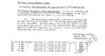
urse translation of the German title. Yes, I know that you have the docu also. I also know who gave it to you. Tests were flown at 3000m. The Mach number given on x-axis with the km/h in some graphs, for ex in Abb. 18 and the roll rate hit the x-axis at bit over M 0.8 / a bit under 1000km/h at 3.000m.
...
Difficult to know the reason of so big difference between US and German data. All I can say as layman on technical matters that Ribnitz'/DVL's data is based on test flight program and had been so interesting that for ex. Kurt Tank had read it among others.
Unfortunately you have chosen to present part of the paper that says what they are looking into not the piece that deals with the investigation. If this is the paper that I read in the entirety, the problem was associated to the change in the COG as new equipment was added to the Mk V which was easily fixed once the problem had been identified.
Claidmore - the wing torses in high speed rolls. The dynamic pressure (Q) applied to the 'up' airleron, for example, creates a force on the aileron that is eccentric to the primary wing axis (visualize a vector parallel to the chord but above the mean chord line or longitudinal centroildal axis of the wing. That force, when translated to the wing does two things.
1.) it creates a vertical force on the aft/outer wing area which causes that wing to deflect downward
2.) it creates a horizontal force above the centroidal axis which causes the wing to twist about the centroidal axis.
It is the latter torsional force which will then tend to create a higher relative angle of attack, and hence increased lift on the wing - thereby counteracting the force imposed by the aileron in the rolling manuever.
So, stiffen the wing to resist the torsional load deflections or decrease the aileron area to decrease the applied Q load on the aileron.
The report doesn't say any such thing. You don't have the report - you were asking for it just a couple of days ago - and you have made the above up.
Thank you! I'ts clear as mud now! lol.
Seriously, aileron reversal was something which I knew about, but had no clue as to what caused it, other than the situations (speeds) that it occured. I've got a glimmer of understanding now.
 If I was to twist the tip forward for example I'd decrease the AoA at the tip in relation to the root I know you know this, just couldn't resist pointing it out for Claidemore's sake.
It does matter which way he twists the tip though, you forgot to say that hehe
What I find interesting is the significant reduction in the limitations at altitude which for a fighter that is reckoned to be in its element higher up must have been a major limitation
I was thinking of the before and after figures, 341 to 280 is by any standard, a drop.
Hi VG-33,
I did not find anything with Google search of "Ostolsawki" or "RDK" or "Kosminkov".
Can you give direct Amazon book links (ISBN number) or internet links.