BarnOwlLover
Staff Sergeant
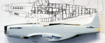
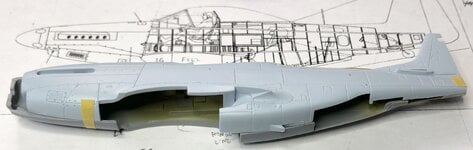
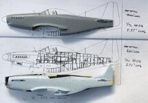
I know that the P-51H was at least a foot longer than the XP-51F/G it was developed from. The added length from what I read was added to try and offset the directional stability problem that the Merlin Mustangs had that became more pronounced in the F/G during testing.
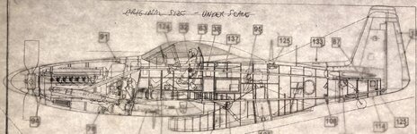
My question is where was the length added. The distance between the tail and the trailing section of the radiator scoop/duct seems about the same (and the ductwork seems to be about the same length). However, for sure, the nose on the P-51H was longer (engine was moved forward several inches for CG reasons). Thus, were was the added length added, and about how much fore vs aft?
My question is where was the length added. The distance between the tail and the trailing section of the radiator scoop/duct seems about the same (and the ductwork seems to be about the same length). However, for sure, the nose on the P-51H was longer (engine was moved forward several inches for CG reasons). Thus, were was the added length added, and about how much fore vs aft?