1:48 Engine Room #3 Battleship USS New Jersey for Permanent Display on Board.

Ad: This forum contains affiliate links to products on Amazon and eBay. More information in Terms and rules

Thanks Fellas!
Design work and printing continue. I'm almost at the end of the design phase. I'm kind of in the punch list arena now.

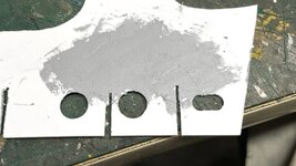
Work also continues on cutting the main framing that supports the whole thing. I went the "patching route" in plugging the errant holes in the fore bulkhead.

 NJ ERP Bulkhead Patches 1.jpg


I filled them with Tamiya filler and will sand the first coat on Monday. Today's my wife's 80 birthday (I married an older women since my 80th is at the end of July) and promised I wouldn't be in the shop today. The rest of the filler is patching the deepest surface scratches that resulted from over-aggressive sanding of plastic cement remnants that I used to hold the stack of frames together for cutting and drilling. I was amazed at just how difficult it was to slice them apart. I'm going to try a different method to do the same on all the cross longitudinal frames. I'm also not going to attempt to cut the slots by sawing. They just wavered too much. I'm having to recut them all with a #11 blade anyway, might as well cut them that way from the start. And I'm using a square to keep them nice and vertical.

NJ ERP Bulkhead Filling 1.jpg


The evaporators are printed and trimmed waiting, along with a ton more stuff, for some paint. I printed them hollowed out to reduce the resin quantity. I also included plugs left over from the hole-drilling task in the slicer. The plugs are a press-fit back in the holes and needing no glue. A quick sanding and the holes disappear. I use a large syringe to wash the resin out of the interiors with IPA.

NJ ERP Evaporator Plugs WIP.jpg


Front view. I chose to simplify the plumbing on these, since I couldn't make any sense of it. Ryan thinks they look great.

NJ ERP Evaporators.jpg


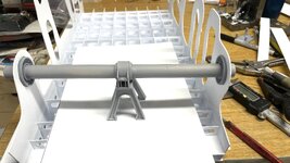
The entry catwalk is hung from the ceiling! It is not fastened to the main reduction gear that lies below. To replicate this, I'm creating a faux ceiling to support it. It will also support the entry hatch which is a feature I didn't want to leave out (not yet designed). All of these frames are sliced and ready to print. None of the framing is a 1:1 replication and asserts a lot of "modele's license". The ceiling structure is more varied than how I'm depicting it, but viewers will understand. I taking advantage of the accurate main support pole in holding up the ceiling structure.

Entry Stair Complex.png


I also lined out the flooring supports for the main control board and the main air ejectors. Both of these are at the fore end of the engine room. Had to fuss a lot to get the support poles to clear all the apparatus below. Again, the flooring is not truly accurate with much of the support would hung on the cutaway fore bulkhed. This is the Air Ejector flooring bracing. Also note the added support on the flooring system running into the picture that holding up the catwalks next to the turbogenerators and electrical decking.

Floor  Bracing.png


And here's the port side floor system.

Floor Bracing 2.png


Lastly, here is the flooring system and electrical console on the slicer and ready for print. This file and the other floor bracing file has been transmitted to the printer and will be print next week. The only reason the main control board's not ready for print is lack of information. I'm waiting on Ryan to send more pictures of it. It such an important feature that I want to make it right. I'm hoping that all the switches and levers on the electrical console print correctly.

Screenshot 2025-04-11 at 2.43.47 PM.png


I've ordered and received most of the electrical materials for the lighting. I'm using surface mount LEDs again, but in this installation, I've gone to cool white to replicate the florescent lighting used in the 1:1 space. I was able to get 200 LED chips for $6.35 plus KY Sales tax from Amazon. That's $.03 a piece. Ridiculous! And they are very, very bright. I redesigned the electrical console with space for the LEDs and their wiring. Lighting is going to fun and challenging. It's also going to add life to all the underneath details.
 

Attachments

  • NJ ERP Bulkhead Patches 2.jpg
    NJ ERP Bulkhead Patches 2.jpg
    871.6 KB · Views: 26
Thanks guys. Missed yesterday's post so today will be a twofer.

First up… thought it would interesting to see the vast number of parts already created for this project. We're at the 95% level. I finished printing the smaller flooring frames and they're waiting for trimming and sanding. I've also uploaded the file to print the remaining large floor frames. I've almsot finished drawing the various electrical cabinets, and Ryan has promised that he'll take pictures of the main gauge board, which is the last piece to be finished. In those plastic boxes are all the floor gratings ladders and diamond plate pieces. All of this and no instructions! I've received all the electrical materials and am going to do some experimentation of soldering on copper foil attached to resin. Resin doesn't melt per ce, but it can burn. If I can it would simplify attaching the surface mount LEDs. The large curvy pipe at the top is the new main steam pipe that has clearance built in to clear that large central pole (resembles a rocket in the foreground).

NJ ERP Lotsa Parts - No Instructions.jpg


I printed the tiny hand wheels for the auxiliary air ejectors. I chose to mount them with 0.015" phos-bronze wire. I had to drill the parts with a 0.016" carbide bit. I got through almost all of them before breaking one. I attmpted to attach the even tinier smaller valve wheel using wire, but it proved ridiculous. I ended up putting them on with CA.

First image shows the valve hand wheel attached to the wire. Note the fine-tipped tweezers for scale.

NJ ERP Aux Air Ejector Hand Wheels.jpg


And the finished parts: Pins are also installed in the pipe ends to faciliate gettimg them attached to the ma
IMG_6747.jpg


I took some time off to rebuild additional lighting on my workbench. I had two of these puck lights left over from an under-cabinet project and used them for a couple of years. The voltage adjuster died rendering them dead. Another under-cabinet job gave me two more surplus LEDs pucks that I added to the one remaining. They're 12vdc units and require no current management circuits. They just need a 12vdc power sorce. I needed another LED power supply for the engine room project so I bought two. I wired them up in parallel and added a toggle switch to activate them. Lots of needed light.

Bench Lights Back On.jpg


The circuitry isn't pretty, but it's solid and safe. That circuit strip needs some craft work to parallel the contacts, but jumpering them. The strips came from when I built my first railroad at our house in Düsseldorf, which explains why their "Euro-style". I used them all over my model railroad and I'm finally running out them. When I decided to build my railroad in our German house, the head of the technical training department at Henkel provided me with an enormous amount of electrical hardware to make it all happen. It was when I learned about crimped ferrules on the ends of wires that are used along with these knds of terminals.
Bench Lights Power Supply.jpg


I printed the electrical control panel in the same run with the miscellaneous floor frames. The frames came out perfectly, but the panel was a failure.

NJ ERP Elec Panel Fail.jpg


The failure was not the printer's fault. It was the draftsman… me. The drawing was flawed. There was a layer underneath the slant panels. The printer/slicer was confused by this inner layer and tried printing both. You can see this inner panel in the centeral area where another slant panel was supposed to go. I went back and fixed all the drawing errors. I printed it again solo, and the results are perfect. It's draining on the printer and I'll finish it up tomorrow. While it's hard to see with all that excess resin covering it, the control knobs and switches did resolve.

NJ ERP Elec Panel Success.jpg


Back to the main floor framing. Oh boy! I wish I could have had it all laser cut. It's been well over a week and I'm still cutting away. I keep refining the process, but it's a lot of heavy duty hand work.

After scribing and snapping all the long cuts, I used the Northwest Short Line Duplicutter 2 to gang scribe the cross-cut length.

NJ ERP Floor Beam Gang Cut.jpg


To make the stack of the fore and aft beams, I used Scotch Double-sided "permanent" tape. It held the stack well enought and came off with no residue or sanding. Using plastic cement was more trouble than it worked.

NJ ERP New Stack Method.jpg


I used a prick punch to locate all the holes and then pilot drilled the with 1/16". it was a bit too small for the big holes, but was perfect for the tops of the cross-lap cuts.

NJ ERP Pilot Drilling.jpg


The big drill was okay… just okay. It wandered on a couple of holes meaning the some of the slots are not parallel to the part edges. Annoying? Yes! Show stopper? No! It's all at the very bottom of the model and recessed from view. Won't be seen much except by me. These holes drilled much better than the ones I did on the abaft ship frames. Part of that was due to holding the stack more firmly with a drill press clamp in additionl to my fingers.

NJ ERP Stack Drilled.jpg


I started cutting the scrap between the holes with the #11. I didn't like how it performed. I switched to a single-edged razor to start the cuts. Worked better, but still not so hot. Finally I used my 90º corner chisel. This worked well. I don't have any straight wood chisels. A 1/4" inch chisel would have been perfect.

NJ ERP Opening Slots.jpg


I started doing trial fits with satisfactory results. There is another, 2nd skin mid-point in the framing. I'm going to add this only in the outer spaces since the inner ones would be invisible. The triple bottom was only used under the hull areas included in the armored citidel.

NJ ERP Trial Fit 2.jpg


You are now all up to date.
 
Fantastic !
It is really incredible how scratch building in modelling has advanced in even the last five years or so. Forty years ago, PE was "new fangled" and limited, resin parts didn't exist, and 3D printing (parts or decals) wasn't even a "pipe dream" !!
 
The electrical control panel exceeded my expectations. The elevated switches on the panel resolved with the levers in the various positions. Now all I have to do is paint the darn thing which could be a lot of fun (or not). The problems were entirely with the drawing. Fix the drawing… fix the part. As close as I could tell from the photographs, the controls are as they are on the real thing, even to their disposition.

NJ ERP Elec Control Panel Perfect.jpg


Work continues slowly on the under-framing. I keep developing better techniques. By the time I finish all of them I'll have it all figured out. I did find a chisel narrow enough to chip out the material between the circles. Even with that, I had to refine how I was chipping it out. Instead of making three separate hacks at it, I found that if I slid the blade down a pre-scribed line (from a #11 blade and straight edge), the removed part had cleaner edges and leaving me with much less cleanup of the openings.

While assembling the array for trial I realized an error was cropping up. The abaft main frames taper from the middle to the edges as the real floor does to let any water to flow towards the bilge wells at the outer corners and be pumped overboard. I, foolishly, wanted to faithfully represent this slant and built it into all of the cross-frames. That meant that all the fore and aft frames, depending on their location, would have differing heights. I built this into the patterns. But… I chose to cut them all from one template meaning they were all the same height. My mom used to say that "G_d protects fools, drunks and little children. In this case he protected the fool. Luckily, the template I chose was the tall middle one. At least I could remove the excess stock on the ones that are shorter out at the edge. It could have happened in reverse and I would have all the middle floors not reaching the tops of the main frames. As i progressed today, I took individual caliper readings and used the digital caliper as a height gauge scribing the correct height so I could shave off the excess.

Putting the frames together was a little like herding cats, so I decided to tack glue some selected joints to stabilize it. One of them was on the "front" bulkhead. Later, as I added more fore and aft frames and then more main frames I found that I had hung the rear bulkhead where the front should go. Again, lucky that I only had one flimsy glue joint to break to make the exchange. I'm glad I'm doing all these trial fits.

NJ ERP Under Framing Glue Start.jpg


Here it is with correct rear frame at the rear. It's going to be a challenge to ensure everything is square. Also, liquid cement is not sufficient to hold the cross laps due to their slop. I will go back and use tube cemnet after everything is tacked in place. The flooring itsellf will be 0.030" styrene sheeting and that will made the whole thing very strong.

NJ ERP Under Frame wIP.jpg


We're heading out of town on Thursday so reports will have to wait until next week.
 
Thanks guys!

We had friends from our old neighborhood in Philly area over for a long weekend, so I got back into the shop today. First of all, the framing and column print from last week, while successful print-wise, won't work model-wise. The I-beam columns I drew and printed, while delicate and scale-like, was too frail to exist in the real world. I changed them to H-beams and doubled their cross-section. That print finished a short while ago and I will clean them up tomorrow. Pictures to come tomorrow.

I spent the rest of the work session cutting out the first skin (ship's bottom) and showly gluing the lattice to it. While at it, I am also adding the 2nd skin on the outsde exposed spaces. There are slight variations in spacing so each 2nd skin piece had to hand measured, cut and fit for a nice glue joint. I'm using both Tamiya thin cement and good old Testor's tube cement due to its gap filling abilities.

I'm employing angle blocks of various sizes to weigh down the lattice and to give a nice square corner while glung. I have to be careful to shim the outside since only part of the block is sitting on the bottom skin and it led to a tipped block. The shim kept the blocks level so the 2nd skin is also level. I haven't glued any of the sides or central lattice yet. I wanted to get the fore and aft bulkheads well attached before gluing the center which will not be seen. I think I've found a spot where I could cut open the floor a bit to show the triple bottom which is so characteristic of a warship like this one.

I started the glueup with the rear bulkhead since it is only sitting on a little lip. I wanted it glued tight. I also cut a 3/8" strip to sit on top of the little lip that remains. This extra piece will give the 3D-printed external stiffening frames a bittle bottom on which to sit.

NJ ERP Bulkhead Gluing.jpg


With the back bulkhead in place, I started working on the front. I'm gluing the bulkhead and the 2nd skin pieces together as I move along. I have a few pieces on the extremis left to finish this step. The upper bulkhead and framing will be white, while all the underneath skins and frames will be red-lead or something akin. The little "tables" are 3D-print fixtures to set the height and level of the 2nd skin. By doing it this way, i didn't need to glue any corner or edge supports to hold the 2nd skins in alignment. Plastic cement does not affect UV resin. These too needed their outer legs to sit on shims to hold them level.

NJ ERP Installing 2nd Skin 1.jpg


Only 3 more 2nd skins need to be added to the fore bulkhead. I will also add 2nd skin pieces to all the open sides and then just a few in the area that's going to be cut away for vieweing.

NJ ERP Installing 2nd Skin 2.jpg
 
The re-designed and re-printed minor flooring frames came out well and the enlarged H-Beam columns now have the structural integrity to support the platforms as I needed. I also added sockets printed with the frames to capture the H-Beams. I made the socket openings slightly larger in all directions so the columns just drop in without forcing. I will use CA to hold them, but use epoxy to glue the columns to the floor system.

NJ ERP H-Beam Socket.jpg


The Main Gauge Board floor system attaches to the larger and more robust frame holding up the evaporators. I made the mating beams so they could nestle into the larger frame. I was rewarded that it fit as I drew it. This frame has four columns although I probably didn't need them since the one end is attached to the larger frame.

NJ ERP Main Gauge Panel Framing.jpg


For the evaporator floor frame and drew some brackets to provide a stronger mount to the Turbo-gen frames and the other free end supported by two H-beam columns.

NJ ERP Main Air Ejector Deck Framing.jpg


Looking underneath you can see the brackets, but they're suffering from a depth-0f-field problem with my iPhone's camera. I have an iPhone 12 Pro. I'm thinking about upgrading and wonder if the iPhone 16 Pro's camera has better custom focus control. I take many closeups among the thousands of images I've made documenting my model building pursuits.

NJ ERP MAE Framing Tie-in.jpg


Meanwhile, I'm putting in more of the 2nd skin floor filler pieces. Only one more side to go. I may have to paint the insides of this before glueing down the hold floor since you can peer through all the holes and see the insides. You won't be able to see whether there's a 2nd skin in there, but you might be able to see all that white styrene. That said, the entire framing interior will be in the dark. So maybe, I won't have to paint it. A couple of the fore & aft frames are sitting a little low. I will shim them before gluing on the floor panels. I want the panels and smooth as possibel since so much has to be fastened to it. Notice the hole cuts in the face of the fore bulkhead to provide passage for the condensate water ram intake. There's a couple of other holes needed in the hold floor for more intakes and discharge ports. I'm not opening up the bottom as the model sits on it and it's not visible.

NJ ERP Bottom Progress.jpg


That narrow fire room floor is necessary for two reasons: a base for the wall stiffeners that are on the boiler room side, and for passage of that ram intake. Everything at hold floor level and below is oxide red, bulheads above that are white. It's really getting excited about thinking about starting construction. Still have two more details I need from Ryan, but I can proceed without them. They are not in the critical path… yet.
 
Interesting day! I got the 2nesd skin inserts done without issue and turned my attention to the entire floor structure. I was thinking about taking it outside to apply the red primer, but I decided instead to start fitting some of the critical items to double check fits before getting ahead of my skis. Boy! Am I glad I did. The port side prop shaft, bearing mount and seals aligned perfectly with the floor (temporary piece of 0.030" stock) and the holes in the fore and aft bulkheds. I was also rewarded with the output shaft lining up perfectly when the high pressure turbine frame, on the other end, aligned. But the starboard side prop shaft didn't align with the seal hole in the aft bulkhead. This would not do.

NJ ERP 2nd Prop Shaft Misfit 1.jpg


NJ ERP 2nd Prop Shaft Misfit 2.jpg


It required some serious surgery and some grafting. I traced the correct location on the bad part and then cut it off by scribing and snapping.

NJ ERP Surgery Start.jpg


I then used it to trace a replacement. I didn't like the lack of stiffness anyway and needed a flange to properly glue the graft in place, so I made the first piece long enough to have a lip that extended down to hold floor level. I cleaned this up and tried it out for fit. It worked well.

NJ ERP 2nd Prop Shaft Refit.jpg


I then used it to trace another piece, but this was had the traced cut line from the severed part so it would closely match the glue line and mitigate excessive filling. After gluing the two together, I finished sanded them as a single laminate. I glued this in place with tube cement and clamped it until set.

NJ ERP 2nd Prop Shaft Rebuild Laminate.jpg


Tomorrow I will finish the joint with filler as needed and make it invisible. With the double thickness, there is now some extra material behind that will have to be accounted for when fitting in the hold floors.

While doing this it became clear that ALL the stiffeners needed to be secured since there would be CA and epoxy that would make a mess of any finished paint surfaces. I started with the fore bulkhead by adding the stiffener for the HP turbine frame. I used thick CA and then added epoxy where it needed more strength on the bottom horizontal piece that simulates the fire room floors.

NJ ERP Fore Blkhd Stiffener Install.jpg


I also added an I-beam to stiffen the wall where the main steam line passes through the bulkhead.

NJ ERP Steam Line Wall Stiffener.jpg


Here are the two stiffeners in place.

NJ ERP Stiffeners Installed on Fore Blkhd.jpg


A top view shows the 3º angle that the main propulsion system sits so it's aligned with the #2 propeller. It's neat to see the parts in place and how they replicate what I've drawn.

NJ ERP Overhead Shot of Major Fits.jpg


Boy, am I glad I put my foot on the brakes and didn't spray any paint. I'll added the stiffeners on the aft bulheads, and then I can spray the base red primer. I will then glue on the hold floor and paint it too. Once the base is prepared, assembly can being in earnest. The weather's warming up so outside paint days will be more frequent.
 

Attachments

  • NJ ERP Prop Shaft Fit Test.jpg
    NJ ERP Prop Shaft Fit Test.jpg
    909.9 KB · Views: 19

Users who are viewing this thread

Back